Raven XE User Guide 20080605 Rev 2.
Preface Important Notice Due to the nature of wireless communications, transmission and reception of data can never be guaranteed. Data may be delayed, corrupted (i.e., have errors) or be totally lost.
Preface DIRECT, INDIRECT, SPECIAL, GENERAL, INCIDENTAL, CONSEQUENTIAL, PUNITIVE OR EXEMPLARY DAMAGES INCLUDING, BUT NOT LIMITED TO, LOSS OF PROFITS OR REVENUE OR ANTICIPATED PROFITS OR REVENUE ARISING OUT OF THE USE OR INABILITY TO USE ANY SIERRA WIRELESS PRODUCT, EVEN IF SIERRA WIRELESS AND/OR ITS AFFILIATES HAS BEEN ADVISED OF THE POSSIBILITY OF SUCH DAMAGES OR THEY ARE FORESEEABLE OR FOR CLAIMS BY ANY THIRD PARTY.
Preface Contact Information Support Desk: Phone: 1-877-231-1144 Hours: 5:00 AM to 5:00 PM Pacific Time, Monday to Friday, except US Holidays E-mail: support@sierrawireless.com Sales Desk: Phone: 1-510-624-4200 1-604-232-1488 Hours: 8:00 AM to 5:00 PM Pacific Time E-mail: MobileandM2Msales@sierrawireless.com Post: Sierra Wireless America 39677 Eureka Drive Newark, CA USA 94560 Sierra Wireless 13811 Wireless Way Richmond, BC Canada V6V 3A4 Fax: 1-510-624-4299 1-604-231-1109 Web: www.sierrawireless.
Contents Introduction to the Raven XE . . . . . . . . . . . . . . . . . . . . . . . . . . . . . . . . . . . . . . . . . .1 ALEOS™ . . . . . . . . . . . . . . . . . . . . . . . . . . . . . . . . . . . . . . . . . . . . . . . . . . . . . . . . . . . . . . . . . . . . . . . 2 AceWare™. . . . . . . . . . . . . . . . . . . . . . . . . . . . . . . . . . . . . . . . . . . . . . . . . . . . . . . . . . . . . . . . . . . . . . 2 Modem Doctor . . . . . . . . . . . . . . . . . . . . . . . . . . . . . . . . . . . . . .
Contents Inputs, Relay Outputs, and Power Status . . . . . . . . . . . . . . . . . . . . . . . . . . . . . 50 Capturing External Events using Inputs . . . . . . . . . . . . . . . . . . . . . . . . . . . . . . . . . . . . . . . . . . . 50 Connecting devices to the IO Port . . . . . . . . . . . . . . . . . . . . . . . . . . . . . . . . . . . . . . . . . . . . . . . . . . . . . . 51 Monitoring the Input and Output . . . . . . . . . . . . . . . . . . . . . . . . . . . . . . . . . . . . . . . . . . . . . . . .
Contents Status . . . . . . . . . . . . . . . . . . . . . . . . . . . . . . . . . . . . . . . . . . . . . . . . . . . . . . . . . . . . . . . . . . . . . . . . 90 Information Displayed in AceManager without AT Commands Listed . . . . . . . . . . . . . . . . . . . . . . . 93 AT Commands Requiring PassThru mode . . . . . . . . . . . . . . . . . . . . . . . . . . . . . . . . . . . . . . . . . . . . . . . 93 Common . . . . . . . . . . . . . . . . . . . . . . . . . . . . . . . . . . . . . . . . . . . . . . . .
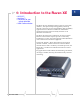
1: Introduction to the Raven XE 1 • ALEOS™ • AceWare™ • Connecting to your cellular provided • GSM Communication The Raven XE is an intelligent wireless gateway, powered by ALEOS™, and optimal for providing primary or backup network connectivity for any high‐reliability/ high‐availability applications.Class I Divison 2 certified as nonincendive equipment, the Raven Series is ideally suited for use in hazardous environments.
Introduction to the Raven XE ALEOS™ ALEOS, the embedded core technology of the Sierra Wireless AirLink products simplifies installation, operation and mainte‐ nance of any solution, and provides an always‐on, always‐ aware intelligent connection for mission‐critical applications.
Introduction to the Raven XE Simplified Deployment AceManager provides the ability to remotely set up and configure your Sierra Wireless AirLink products. Remote device setup and configuration reduces the deployment timeline of your wireless solution and provides a quicker path to ROI. Templates allow you to easily configure other devices in your fleet with identical settings, ensuring a simple, accurate deployment.
Introduction to the Raven XE Modem Doctor Modem Doctor is a troubleshooting and diagnostics utility. This utility will allow you to get a log file of the Raven XE activity which you can then send to Sierra Wireless support, erase the current configuration completely., and temporarily set the Raven XE to a known configuration to aid in trouble shooting (SOS mode).
Introduction to the Raven XE Raven XE Figure 1-4: Connecting to the Internet The Raven XE will perform a one‐to‐one routing for all internet traffic to and from the computer or other end device. One‐to‐one means that your Raven XE will provide a connection for one device to the Internet at a time. In Private Mode, the Raven XE will provide NAT (Network Address Translation) for the computer or other end device.
Introduction to the Raven XE Tip: If your account with your cellular provided includes a dynamic IP address and you need a static IP, please consult your your cellular provided Representative for more information about changing your account for static IP support.
Introduction to the Raven XE from Node B (known as HARQ‐Hybrid Automatic Repeat Request) to deliver the improved downlink performance vs. UMTS and EDGE. HSPDA (and HSUPA) falls back to UMTS, EDGE or GPRS (in order of precedence). This feature allows you to have seamless connectivity no matter where your Raven XE is. UMTS UMTS (Universal Mobile Telecommunications System) supports up to 1920 kbit/s data transfer rates, although most users can expect performance up to 384 kbit/s.
2: Specifications 2 • Power Connector Features and Benefits • Embedded Intelligence • Low Power Consumption • Compact Size • Rugged Aluminium Case • High‐Speed Processor (ARM 9) • High‐Speed 2‐way Data • 10/100 Mbps Ethernet Port • Persistent Network Connectivity • Remote Management and Configuration • Class I Div 2 Certified Technology • HSUPA With Fallback to: · HSDPA · UMTS · EDGE · GPRS (MS‐12) · GSM Bands • TriBand for UMTS/HSDPA/HSUPA · 850/1900/2100 MHz • Quad Band GPRS/EDG
Specifications Standards/Approvals • Carrier specific approvals • CE (Class A device per EN55022) • RoHS • FCC • Industry Canada • PTCRB • This apparatus is suitable for use in Class I, Division 2, Groups A, B, C, D or unclassified or non‐hazardous locations. • CE • PTCRB Warning: Explosion Hazard - Substitution of any components may impair suitability for Class I, Division 2.
Specifications • Signal • Activity • Power • Reset Button Power Connector Digital I/0 4 3 Digital 2 Ground (black) 1 I/O Power (red) Power (red) Ground (black) Figure 2-1: Power Connector (not to scale) Warning: Explosion Hazard - Do not disconnect equipment unless power has been switched off or the area is known to be non-hazardous. Note: Raven XE I/O Port 4 is software configurable. Rev 2.0 Jul.
3: Activating Raven XE on your cellular provided 3 • Installing the SIM • Configuring the APN This chapter provides step‐by‐step directions for activating your Raven XE on your cellular provided’s network. H Installing the SIM The Subscriber Identity Module (SIM) in the Raven XE is a smartcard that securely stores the key identifying a cellular subscriber. Generally, you will only need to install a SIM once in the life of the modem and it may be pre‐installed by your Sierra Wireless Representative. 1.
Activating Raven XE on your cellular provided Tools Required • Small Phillips screw driver ‐ The Phillips screw driver is the one which is also called a plus (+) or X screw driver. • Slim stylus ‐ A PDA stylus, an unbent paperclip, or other such item. Figure 3-1: Faceplate Warning: Explosion Hazard. Do Not remove or replace Plug-in Modules unless power has been disconnected or the area is known to be free of ignitible concentrations of flammable Gasses or vapors. 1. Opening the Case a.
Activating Raven XE on your cellular provided Figure 3-2: Sample of the SIM card 3. Insert the SIM a. Gently press the SIM card to click it into place. Tip: The top of the card faces the bottom of the modem. Note: The card and SIM may be a different color than these examples. Figure 3-3: Insert SIM in to the modem 4. Finishing the SIM installation When the faceplate is replaced and secured, the installation of the SIM is complete. Secure the front of the Raven XE with the screws. Rev 2.0 Jul.
Activating Raven XE on your cellular provided Configuring the APN The APN (Access Point Name) is the way your modem knows how it will be communicating with the network. The APN allows custom IP addressing and tailoring your companyʹs wireless IP solution to meet the security and IP addressing requirements of your applications. Note: Most accounts use the default addressing solution of Private or Public IP addresses supplied by the Internet and Proxy APNs.
Activating Raven XE on your cellular provided b. Select PPP. c. Select TCP or UDP. d. Enter the connection information. · For UDP or TCP, enter 192.168.13.31 as the IP address. · For PPP, select the COM port to which the modem is connected. e. Enter the password. The default password will be entered for you. f. Select OK. 3. Enter the APN a. Select EDGE/HSDPA/HSUPA from the menu on the left side of AceManager (under “Groups”) Figure 3-5: AceManager : EDGE/HSDPA b.
Activating Raven XE on your cellular provided · For PPP, select the COM port to which the modem is connected. f. Enter the password. The default password will be entered for you. g. Select OK. Optional: If you need to configure your modem for a cus‐ tom APN, after entering the APN, there is additional infor‐ mation you will need to enter. 1. Select Misc from the menu on the left side under the Common group. Figure 3-7: AceManager : Misc 2.
Activating Raven XE on your cellular provided Figure 3-9: AceManager : Write c. Rev 2.0 Jul.09 Reset the Raven XE.
4: Hardware Installation of the Raven XE 4 • Connecting to Power • Connecting to a Computer or other Device • Indicator Lights • Mounting Note: During installation, please be sure that the cables are secure but do not bear any additional weight that could loosen the connector from the unit. Your Raven XE should be mounted in a position that allows easy access for the cables so they are not bent, constricted, in close proximity to high amperage, or exposed to extreme temperatures.
Hardware Installation of the Raven XE Your Raven XE will work with most PCS cellular antennas with a SMA connector that works in the high and low frequencies of the cellular technology of your modem. Connect the primary antenna or primary RF cable directly to the antenna connector on the back of the Raven XE. Tip: When using a cable to an antenna placed away from the modem, minimize the length of your cable. All gain from a more advantageous antenna placement can be lost with a long cable to the modem.
Hardware Installation of the Raven XE Note: When using a DC power source (such as a solar cell), Sierra Wireless recommends placing a fuse (1-2 Amp) on the line close to the power source to protect your power source from possible surges due to shorts or other line issues. The DC power cable positive lead should be connected to the battery or power source positive terminal. The power cable negative lead should be connected to the battery or power source negative terminal.
Hardware Installation of the Raven XE Figure 4-4: USB Your Raven XE’s full‐speed (12 Mbit) USB 2.0 port can be connected directly to most computers or other devices using a standard full‐speed USB 2.0 cable. If the computer or device you are connecting or the cable is not rated for full‐speed, the modem will communicate at a reduced speed to match. The Raven XE functions as a device, not a host.
Hardware Installation of the Raven XE RSSI LED Ranges RSSI/Signal LED Status Ranges of RSSI (dBm) On Solid Equal to or stronger than -69 Fast Blink -70 to -79 Normal blink -80 to -89 Slow Blink -90 to -99 Extinguished Equal to or weaker than -100 • Activity ‐ Lights will flash as data is transferred to and from the PinPoint modem on the remote network. • Power ‐ Indicates the power adapter is connected and there is power getting to the Raven XE.
Hardware Installation of the Raven XE Mounting An optional accessory for your Raven XE is a mounting kit, which includes a bracket. The bracket is designed to snugly cradle the modem and hold it in place where you need it. You can use a strap around the bracket and modem for extra security. The bracket can be attached to a stationary location using #6 screws with the mounting hole diameter approxi‐ mately 0.150ʺ. The instructions to bracket installation is following: 1.
Hardware Installation of the Raven XE Figure 4-7: Mounting bracket installation Rev 2.0 Jul.
Hardware Installation of the Raven XE Figure 4-8: 100-170-1015 : Mounting Bracket for Raven XE Rev 2.0 Jul.
5: Configuring your Raven XE • Using AceManager • Using Templates • Using a Terminal Application with AT Commands 5 With ALEOS as its “brain”, the Raven XE is a highly configu‐ rable device, more than just a “dumb” modem. To configure your Raven XE, you have two options. You can use the configuration and management applications of the AceWare suite or you can use a terminal emulator application such as HyperTerminal, PuTTY, or many others.
Configuring your Raven XE Figure 5-1: AceManager 2. Connect to your Raven XE a. Click the Connect button. Figure 5-2: AceManager : Connect to Modem b. Select a connection method: · If you are connecting remotely, you can use UDP, TCP, or SMS. · If you are connecting locally with the modem connected directly to your computer using a serial cable, you can use PPP. · If you are connecting locally with the modem connected directly to your computer using an Ethernet cable, you can use UDP, TCP, or Ethernet.
Configuring your Raven XE e. Select OK. Figure 5-3: AceManager : Connected 3. Enter the configuration options a. On the left side of AceManager is the Groups menu. Select the appropriate group as needed or directed. Rev 2.0 Jul.09 b. Enter your changes in the New Value column by typing in the desired change or using the drop down menus. c. The current configuration is shown in the Value column.
Configuring your Raven XE Figure 5-4: AceManager : Changing values 4. Write the changes to the modem a. Click the Write button on the tool bar of AceManager. b. Wait for the message “Write Successful” to appear in the status bar. Figure 5-5: AceManager : Write Tip: Some configuration settings will require you to reset the modem before they will take effect. You can reset the modem by using the Reset button in AceManager or by using the reset button on the modem.
Configuring your Raven XE Note: Some of the configuration settings are specific to individual modems. You do not want to have those settings in your saved template otherwise the modems you configure with the template could cease to work with the cellular or local network. · Cellular Technology specific settings ( EDGE/HSDPA group) · *MODEMNAME · *HOSTPRIVIP · *HOSTPEERIP · *HOSTUID · *HOSTPW d. Click the Save button on the toolbar. e.
Configuring your Raven XE 2. Applying a Template to one modem with AceManager You can use a template you created yourself, using the steps above, or a template provided by your AirLink representative or someone in your company who has set up a modem template. The template you wish to apply must be saved to your hard drive. a. Load the template. 1. Connect to the modem you want to configure using AceManager. 2. Click on the Load button on the toolbar. Figure 5-8: AceManager : Load 3.
Configuring your Raven XE Tip: You can use common settings on one modem to configure those same settings on another modem even of a different type. For example, you can use the serial settings of a modem (such as PinPoint X or Raven X) to configure the serial settings of a Raven XE. Settings not applicable to the modem on which you are loading the template, will be discarded. 3.
Configuring your Raven XE Figure 5-10: AceNet : Selected modems Tip: Click on the first with your mouse and, with the control button held down, click the additional modem. b. Select the Modem option in the tool bar and then select Apply AceManager Template. Figure 5-11: AceNet : Modem menu c. Rev 2.0 Jul.09 Either type in the Template file name, or click browse and select the template file you want to apply (you may need to change folders).
Configuring your Raven XE Figure 5-12: AceNet : Template select d. Set the Retry Interval and check if you want to have the modems Reset when the template has been applied. Using a Terminal Application with AT Commands You can access and configure your Raven XE using a terminal application such as Microsoft HyperTerminal, PuTTY, or similar. The following directions are for HyperTerminal which is part of a standard installation of Windows XP.
Configuring your Raven XE Figure 5-13: HyperTerminal 1. Choose a name and icon for your connection. a. Choose a name for your connection, such as Raven XE or Sierra Wireless AirLink Solutions. The name and icon are only for your own reference so you can find the connection at a later date. Tip: If you want to have a connection saved for both local and remote, it is recommended the connection name reflect the connection type, i.e. Raven XE local. b. Select OK. Rev 2.0 Jul.
Configuring your Raven XE 2. Connect To Figure 5-14: Connect To a. Select TCP/IP (Winsock) for “Connect Using”. b. Type in 192.169.13.31 for Host Address. c. Change the “Port Number” to 2332. d. Select OK. Rev 2.0 Jul.
Configuring your Raven XE 3. Connected Figure 5-15: HyperTerminal : TCP/IP connected Figure 5-16: HyperTerminal : connected a. If you are prompted for a password, enter 12345. b. Type AT and press Enter. You should get a reply of “OK” or “0”. a. Type AT and press Enter. You should get a reply of “OK” or “0”. Rev 2.0 Jul.
Configuring your Raven XE b. To see what you are typing as you type it, you will need to turn on the echo and verbose mode. Type ATE1V1 and press Enter. c. If you get a reply of “OK”, then you entered the command successfully. If you get a reply of “0” or “ERROR”, try entering the command again. AT Commands When using a terminal application, you will need to manually type in each command.
6: Universal Serial Bus (USB) • Changing the USB port communication • Installing the USB driver • Using the Virtual Ethernet Port • Using the Virtual Serial Port 6 The Raven XE is equipped with a USB port which increases the methods by which you can send and receive data. The USB port can be set to work as either a virtual Ethernet port or a virtual serial port. A driver installation is required to use the USB port in either mode. Note: It is recommended that you use a USB 2.
Universal Serial Bus (USB) Figure 6-1: AceManager : USB By default, the port is set to work as a virtual Ethernet port (*USBDEVICE=1). To change the USB port to allow virtual serial port communi‐ cation, set *USBDEVICE to 0. To disable the USB port, set *USBDEVICE to 2. Note: If you use a terminal connection with the USB port to change *USBDEVICE, the change is immediate. Your connection will be terminated after inputting the command. Installing the USB driver 1.
Universal Serial Bus (USB) 2. Connect the Raven XE to your computer’s USB port When you connect the Raven XE for the first time to a USB port on your computer, Windows should detect a new device and prompt you to install the driver. Note: Windows will see each port type as a different USB device and will see every port on your computer separately. If you change the port type on the Raven XE or connect to a different USB port on your computer or hub, Windows will see it as a new device.
Universal Serial Bus (USB) · If you have installed AceManager or the Setup Wizard, the drivers have been conveniently copied to your hard drive. Enter C:\Program Files\Common Files\AirLink as the location to search. · If you will be installing the driver from a file downloaded from the Sierra Wireless website, select Include this location in the search and type in the location where you downloaded the file. b. Click Next.
Universal Serial Bus (USB) Note: If you are already connected to the modem with an Ethernet cable, when you complete the installation of the USB Ethernet driver, your computer will not use the USB connection initially. You may need to reboot your computer before you can use the USB port as an Ethernet connection to the modem. 4. Optional: Verify and Configure the Virtual Port Settings Virtual Ethernet The USB Ethernet connection will show up in your Network Connections as a Local Area Connection.
Universal Serial Bus (USB) Figure 6-8: System Properties d. Click on the + in front of Network Adapters. The newly installed driver, AirLink USB Ethernet/RNDIS, should be displayed. If the driver is displayed with a # and number behind the driver name (such as, AirLink USB Ethernet/RNDIS #2), it means more than one is installed on your computer, most likely for different USB port. More than one copy of the driver should not cause any problems since only the connected port and its driver would be active.
Universal Serial Bus (USB) Virtual Serial You can verify the installation by looking in the Device Manager. a. Click on Start > Control Panel. b. Double‐click on the System icon. c. Select the Hardware tab and click the Device Manager button. Figure 6-10: System Properties d. Click on the + in front of Modems. The newly installed driver, AirLink USB Serial Port, should be displayed.
Universal Serial Bus (USB) Figure 6-11: Device Manager - Serial To connect to the modem using the USB virtual serial, most applications or utilities will require you to select or enter the serial (COM) port number. The USB connection will appear as a standard serial port, so you will need to determine its number to connect to it. The driver installation will automati‐ cally assign a port or you can change it if you wish to another unused port. a.
Universal Serial Bus (USB) Figure 6-13: Driver Properties c. At the bottom of the screen, the current port used will be listed. Use the drop down menu to select an available COM port number if you need to change it. Figure 6-14: Advanced Settings Note: The COM port number assigned by driver installation is the next port that is available.The port number might vary depending on the number of devices connected (using serial or virtual serial).
Universal Serial Bus (USB) Using USB Ethernet with AceManager In AceManager, use the UDP or TCP connection and enter the IP address of the modem (192.168.14.31 by default) and the password (12345 by default). 192.168.14.31 Figure 6-15: AceManager : TCP Using USB Ethernet with a Terminal Emulation Utility Configure your terminal application for telnet communication. a. In HyperTerminal, select TCP/IP (Winsock) b. Use the IP address of the modem (192.168.14.
Universal Serial Bus (USB) Using the USB virtual serial port with AceManager In AceManager, the USB virtual serial port connection will appear as a standard serial port. Use the PPP connection and select the COM#serial port of the USB connection. Figure 6-17: AceManager : PPP Tip: You will need to open AceManager after you connect the USB cable to your computer for AceManager to have access to the USB Serial PORT. Using the USB virtual serial port with a Terminal Emulation Utility a.
7: Inputs, Relay Outputs, and Power Status 7 • Sub-section • Sub-section The Raven XE has special features for use in and M2M environment. The Raven XE can be configured to monitor the inputs and respond to specific types of events. These features can be configured to your needs. Capturing External Events using Inputs As part of its power connector, the Raven XE is equipped with an I/O interface for use in instrumentation applications.
Raven XT Figure 7-2: Digital Input Contact Closure • When a door or other latch is opened or closed. • Counting pulses or other electronic events. • When a gauge reaches a certain point. • When a container fills or empties. • When a switch or valve is opened or closed. • When the tow bar is raised or lowered. • Connected to a sensor, the level of fuel in a vehicle. • When the trunk of a vehicle is opened or closed. • When the ignition is turned on or off.
Inputs, Relay Outputs, and Power Status Figure 7-3: I/O Connector Diagram Caution: Never apply voltage to the Digital inputs. The inputs can only be switched open or closed to ground. Monitoring the Input and Output You can monitor the status of the digital inputs using ACEmanager, AT Commands, or with special reports sent by email, SMS, or other report types using Event Reporting. In ACEmanager, select the I/O group. Rev 2.0 Jul.
Raven XT Figure 7-4: ACEmanager : I/O Power Effect on device State Once the transition from powered on to standby, low‐power mode starts, the device will change state to AT mode. This results in the current mode being gracefully terminated. For the brief period when the device is preparing for low‐power mode, the device will remain in AT mode. At that time, it wonʹt auto‐answer, ATD will fail, etc. Once low‐power mode is entered, the device will then discard any data received on the host port.
8: Data Communication and Host Modes 8 • Basic Modes • Data Communication The Raven XE plays the part of a HOST when a computer or another device is connected directly to its port and routes data to/from the connected device to the cellular network. Caution: The Raven XE moves data from one port to the cellular network in a simple one-to-one routing. It does not employ a routing table or any complicated routing protocol.
Data Communication and Host Modes Basic Modes AT Mode Using a terminal connection, AT commands are used to configure the modem, command it to do something, or query a setting. For a full listing of the AT commands, refer to the appendix. AceManager is a graphical user interface for most AT Commands. • AT commands must always be terminated by (ASCII character 0x0D), a carriage return (pressing enter on the keyboard). Some may also include a new line or line feed .
Data Communication and Host Modes PassThru Mode In PassThru mode, the Raven XE does not behave normally, all port communication is passed directly between the internal hardware and the computer connected directly to the modem. This mode can be used to configure hardware‐specific settings. For example, provisioning, troubleshooting, communicating with legacy equipment, etc. Caution: ALEOS is disabled in PassThru Mode. You cannot use most ALEOS specific commands while the modem is in PassThru Mode.
Data Communication and Host Modes Figure 8-1: AceManager : PassThru PassThru Mode allows only specific AT commands. Some ALEOS commands will be unavailable when the Raven XE is in PassThru mode. The commands usable also depend heavily on the modem model number (found on the label on the top of the Raven XE). Note: Some internal hardware requires upwards of 20 seconds before AT commands can be entered, so be patient if there seems to be no response to AT commands.
Data Communication and Host Modes Figure 8-2: AceManager : S0 If you need to change the port for Telnet (for example, you have the default port blocked on your firewall), the option is on the Other tab. The default telnet port is 2332. You can also change the Telnet timeout, if the connection is idle, default 2 minutes. Figure 8-3: AceManager : Other - *TPORT, *TELNETTIMEOUT. Rev 2.0 Jul.
Data Communication and Host Modes Data Communication Note: The Raven XE forwards messages to and from the cellular network for only ONE device per port. The Raven XE is a one-to-one gateway and does not have advanced routing features required to do one-tomany routing. The primary purpose of the Raven XE is to forward data from a single device connected to one of the ports to the cellular network and, ultimately, under most circumstances, to the Internet in a one‐to‐one gateway configuration.
Data Communication and Host Modes Figure 8-4: AceManager: PPP/Ethernet • *HOSTPRIVMODE ‐ Set to 1 to enable the explicit IP addresses. • *HOSTPRIVIP ‐ Set to the IP address you want the Raven XE to give to your device. • DHCP network Mask ‐ The subnet mask that is passed to the DHCP client on the Host device. • *HOSTPEERIP ‐ Set to the IP address you want for the Raven XE. • *HOSTNETMASK ‐ Set to the subnetmask, generally 255.255.255.0.
Data Communication and Host Modes Note: Regardless if the Raven XE is configured for Public Mode or Private Mode, the same IP address will be given to all devices connected to any of the ports. While you can connect with each to the cellular network and the Internet, you cannot use the Raven XE as a hub or router to communicate between them. Internal DHCP Server DHCP (Dynamic Host Configuration Protocol) has become a primary component of today’s network environments.
Data Communication and Host Modes Additional Connected Networks If you have a router connected to the Raven XE with additional networks configured behind that router, you can specify them in the PPP/Ethernet group of AceManager. Configure the Network the Host Network Mask for up to two additional networks. Basic Routing Expanding the capabilities of the Raven XE, ALEOS features some basic routing to connected computers and networks..
Data Communication and Host Modes Figure 8-6: Port Forwarding In AceManager, enter the fields in the Port Forwarding group. • Number of PF Entries: Set value to number of used Port forward rules for performance gain. Each forwarding entry has four parameters: · Public Port: Port number of the Modem/Gateway. · Host/IF: Physical connection type to the modem. (USB, Ethernet). Serial PPP is not available on the Raven XE. · Host IP: IP address of the connected device/computer.
Data Communication and Host Modes Firewall Functions The Raven XE can provide a basic firewall between the public and private networks. There are two types of firewall rules supported by the Raven XE, IP filtering and port filtering. • IP Filtering: When enabled, only packets with source IP addresses matching those in a list or range of trusted hosts will be allowed through. · Friends List IP: Each entry can be configured to allow a single IP address, for example 64.100.100.
Data Communication and Host Modes Figure 8-8: AceManager: Firewall - IP Note: Port Filtering Mode does not require to be set when you enable Non-Friends Port Forwarding. Rev 2.0 Jul.09 • Port Filtering Mode: Independent of the IP filtering, this mode can be enabled to block ports specified or allow ports specified. When enabled, all ports not matching the rule will be allowed or blocked depending on the mode.
Data Communication and Host Modes Figure 8-9: AceManager: Firewall Ports Rev 2.0 Jul.09 • Firewall Port: Specify the port you wish to have blocked or allowed, depending on the mode configured. • Packet Filtering: Not available at this time.
Data Communication and Host Modes Figure 8-10: AceManager: Firewall Keepalive Keepalive is used to test the connection to the cellular network by pinging an IP address after a specified period of inactivity. Keepalive is only recommended for users who have a remote terminated modem that infrequently communicates to the network or if you have experienced issues over time where the modem can no longer be reached remotely.
Data Communication and Host Modes Figure 8-11: AceManager : Other • *IPPING sets the interval, in minutes, you want Keepalive to test the network connection. To disable Keepalive, set *IPPING to 0 (default setting). Note: 15 minutes is the minimum time which can be set for Keepalive. If you set *IPPING for a value less than the minimum, the minimum value will be set. • *IPPINGADDR sets the IP address you want to use for the connection test.
Data Communication and Host Modes Data usage using Keepalive Keepalive is an optional feature. If you frequently pass data with your modem, you most likely do not need to have Keepalive enabled. When using Keepalive, be aware that a ping moves approximately 66 bytes of data over the network and is billable by your cellular provided. The following *IPPING settings will incur approximate monthly data usage in addition to any other data usage: *IPPING Rev 2.0 Jul.
9: IP Manager • Understanding Domain Names • Using IP Manager with your Raven XE • Understanding DNS 9 If you have a fleet of Sierra Wireless AirLink modems or even if you only have one, it can be difficult to keep track of the current IP addresses, especially if the addresses aren’t static but change every time the modems connect to Provider. If you need to connect to a modem, or the device behind it, it is so much easier when you have a domain name (car54.mydomain.com, where are you?).
IP Manager • Dynamic IP addresses are granted only when your Raven XE is connected and can change each time the modem reconnects to the network. • Static IP addresses are granted the same address every time your Raven XE is connected and are not in use when your modem is not connected. Since many cellular providers, like wire‐based ISPs, do not offer static IP addresses or static address accounts cost a premium vs.
IP Manager need to be registered with ICANN or any other registry. It is the responsibility of a domain to keep track of its own subs. car54.mydomain.com • .com is the TLD • mydomain is the domain (usually noted as mydomain.com since the domain is specific to the TLD) • car54 is the subdomain or server name associated with the device, computer, or modem registered with mydomain.com car54.mydomain.com.ca This would be the same as above, but with the addition of the country code.
IP Manager Note: The fully qualified domain name of your Raven XE will be a subdomain of the domain used by the IP Manager server. Using IP Manager with your Raven XE To allow your Sierra Wireless AirLink modem to be addressed by name, the modem needs to have a minimum of three elements configured. You can also configure a second dynamic server as a backup, secondary, or alternate server. In AceManager, select Dynamic IP. Figure 9-1: AceManager: Dynamic IP Rev 2.0 Jul.
IP Manager • *MODEMNAME : The name you want for the modem. There are some restrictions listed below for the modem name. • *DOMAIN : The domain name to be used by the modem. This is the domain name of the server configured for *IPMANAGER1. • *IPMANAGER1 : The IP address or domain name of the dynamic DNS server which is running IP Manager. • *IPMANAGER2 : The secondary server for the domain. While it is optional to have two servers configured, it is highly recommended.
IP Manager Each update is a total of 68 bytes from the modem with a 50 byte total response from the server for a round trip update of 118 bytes. interval (minutes) total bytes per day (24 hours) 10 16992 bytes 30 5664 bytes 60 2832 bytes 500 339.84 bytes Eairlink.com As a service, Sierra Wireless maintains a IP Manager servers which can be used for any AirLink modem.
IP Manager internal to the local network or frequently changing IP addresses, the DNS servers provided by Provider should be all you need.
IP Manager The “PPP-Peer” Domain Name The Raven XE uses the unqualified domain name of “ppp‐ peer” when it is in PPP or SLIP address mode to resolve the address of the device or computer connected via PPP or SLIP address. If the Raven XE is not in PPP or SLIP address mode, “ppp‐peer” will resolve to 0.0.0.0. Rev 2.0 Jul.
10: SNMP : Simple Network Management Protocol • SNMP Configuration • SNMP MIB Definition Sample 10 The Simple Network Management Protocol (SNMP) was designed to allow remote management and monitoring of a variety of devices from a central location. The SNMP management system is generally composed of agents (such as your Raven XE, a router, a UPS, a web server, a file server, or other computer equipment) and a Network Management Station (NMS) which monitors all the agents on a specific network.
SNMP : Simple Network Management Protocol SNMP Configuration To configure your Raven XE to work as an SNMP agent, you can use either AceManager, or a terminal connection to configure the modem using AT commands. In AceManager, the SNMP commands are all part of the Other group under the Common group. There are only three commands to set for SNMP in the Raven XE: the listening port, the security level, and the trap desti‐ nation. Figure 10-1: AceManager : Common > Other Rev 2.0 Jul.
SNMP : Simple Network Management Protocol Listening Port *SNMPPORT sets the port for the SNMP agent to listen on. If set to zero, default, SNMP is disabled. Tip: SNMP generally uses port 161, however most Internet providers (including cellular) block all ports below 1024 as a security measure. You should be able to use a higher numbered port such as 10161. Security Level *SNMPSECLVL sets the security level and which version of SNMP communications are used. • 0 ‐ No security required.
SNMP : Simple Network Management Protocol Figure 10-2: AceManager : Change Password menu option The current password will be pre‐entered. As you type the new password and confirm it, the characters you type will be obscured by “x”. For the password, you can use numbers, letters, and/or punctuation. Figure 10-3: Change Password Caution: The password is case sensitive. “drowssaP” is not the same as “drowssap”. Trap Destination *SNMPTRAPDEST needs to be set with the destination IP and port.
SNMP : Simple Network Management Protocol Community String The community string can be configured using *SNMPCOM‐ MUNITY. The default is “public”.
SNMP : Simple Network Management Protocol ::= { general 4 } aleosSWVer OBJECT-TYPE SYNTAX DisplayString MAX-ACCESS read-only STATUS current ::= { general 5 } aleosHWVer OBJECT-TYPE SYNTAX DisplayString MAX-ACCESS read-only STATUS current ::= { general 6 } modemSWVer OBJECT-TYPE SYNTAX DisplayString MAX-ACCESS read-only STATUS current ::= { general 7 } modemHWVer OBJECT-TYPE SYNTAX DisplayString MAX-ACCESS read-only STATUS current ::= { general 8 } -- COMMON -date OBJECT-TYPE SYNTAX DisplayString MAX-AC
SNMP : Simple Network Management Protocol MAX-ACCESS read-only STATUS current ::= { common 4 } netPW OBJECT-TYPE SYNTAX DisplayString MAX-ACCESS read-only STATUS current ::= { common 5 } requestPAP OBJECT-TYPE SYNTAX INTEGER { no(0), yes(1) } MAX-ACCESS read-only STATUS current ::= { common 6 } destinationAddress OBJECT-TYPE SYNTAX DisplayString MAX-ACCESS read-only STATUS current ::= { common 7 } destinationPort OBJECT-TYPE SYNTAX INTEGER(0..
SNMP : Simple Network Management Protocol STATUS current ::= { status 1 } netState OBJECT-TYPE SYNTAX DisplayString MAX-ACCESS read-only STATUS current ::= { status 2 } netChannel OBJECT-TYPE SYNTAX INTEGER MAX-ACCESS read-only STATUS current ::= { status 3 } rssi OBJECT-TYPE SYNTAX INTEGER(-125..
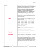
SNMP : Simple Network Management Protocol MAX-ACCESS read-only STATUS current ::= { gps 1 } satelliteCount OBJECT-TYPE SYNTAX INTEGER MAX-ACCESS read-only STATUS current ::= { gps 2 } latitude OBJECT-TYPE SYNTAX DisplayString MAX-ACCESS read-only STATUS current ::= { gps 3 } longitude OBJECT-TYPE SYNTAX DisplayString MAX-ACCESS read-only STATUS current ::= { gps 4 } END Display Responses The string that is displayed for these objects is the same display for the corresponding AT Command. Object Rev 2.
SNMP : Simple Network Management Protocol Object AT Command netPW *NETPW? requestPAP *HOSTPAP? destinationAddress S53 destinationPort S53 serialPortSettings S23 serialPortFlowControl \Q ipAddress *NETIP? netState *NETSTATE? netChannel *NETCHAN? rssi *NETRSSI? serialSent not applicable for Raven-E serialReceived not applicable for Raven-E hostMode *HOSTMODE? powerMode *POWERMODE? PinPoint line modems only fixObtained PinPoint line modems only satelliteCount PinPoint line mod
A: Configuration Commands • • • • • Info (information) Status Common Logging Edge/HSUPA A The configuration commands (AT commands) in this chapter are arranged according to their placement in AceManager. The commands available in AceManager will depend of the model number of your Raven XE and, in some cases, the version of the ALEOS firmware installed. Note: Some commands can only be configured using a terminal emulation and typed AT commands. Some commands also require PassThru mode.
Raven XT Figure 1-1: AceManager : Info *DEVICEID? The 64‐bit device ID the modem uses to identify itself to the cellular network. *ETHMAC? The MAC address of the Ethernet port. *NETPHONE? The modemʹs phone number, if applicable or obtainable. &V View active profile, the contents of the active registers. Not displayed with AceManager. In 89 • n=0 : Product name (for example, Raven XE). • n=1 : The Raven XE’s firmware (ALEOS) version, hardware ID, and copyright.
Configuration Commands • n=3 : The hardware moduleʹs unique identification number or serial number. • n=5 : View active profile (the contents of the active registers). Not displayed with AceManager. Information Displayed in AceManager without AT Commands Listed • Versions of ALEOS, internal hardware, boot, and MSCI: Versions of internally configured hardware and software. Status Most of the commands in the “Status” group have read‐only parameters and provide information about the modem.
Raven XT Figure 1-2: AceManager : Status *HOSTMODE? The current host mode (AT, PPP, UDP, etc.). If the Raven XE is not in AT mode, telnet into the modem to execute this command. *NETERR? The EDGE or GPRS network bit error rate. *NETIP? Note: If there is no current network IP address, 0.0.0.0 may be displayed. The current IP address of the modem reported by the internal module, generally obtained from your cellular provided. This is the address can contact the Raven XE from the Internet.
Configuration Commands *NETOP? The current cellular carrier from the modemʹs firmware version, for example, your cellular provided. *NETRSSI? The current RSSI (Receive Signal Strength Indicator) of the Raven XE as a negative dBm value. Tip: The same information is displayed with the command S202?. *NETSERV? The type of service being used by the modem, for example Tech.
Raven XT +RCIQ Current Cell Info Information. GPRS or EDGE Only. Information Displayed in AceManager without AT Commands Listed • Bytes and Packets Received and Sent: Network traffic for the applicable port. • Number of System Resets: Counter of the number of system resets over the life of the modem or since the configuration was reset. • Bad Password Count: Counter of the number of bad password attempts. • IP Reject Count or Log: Rejected IP Data.
Configuration Commands Common The groups under the heading Common encompass those commands that are common to most Sierra Wireless AirLink modems. For example, a Raven X or PinPoint X will include groups with serial related commands, however, the Raven‐E will not. Misc (Miscellaneous) The commands of the “Misc” group are a variety of commands that don’t directly fit in other categories.
Raven XT A/ Note: A/ is not proceeded by AT. Re‐execute last command. A/ is not used in AceManager. A Manually answer an incoming connection. A is not used in AceManager. D[method][d.d.d.d][/ppppp] or D[method][@name][/ ppppp] Dial a connection to a remote IP and Port using method. Cannot be configured in AceManager. • method=P : Establish a UDP connection • method=T : Establish a TCP connection • method=N : Establish a Telnet connection • d.d.d.
Configuration Commands DS=n Allows a PPP connection to be initiated on the host port. • n=2 : Initiates the PPP connection. Cannot be configured in AceManager. Hn Hang‐Up Command. • n=1 : Hang‐up With an AT telnet connection, this command will terminate the host data mode and return the Raven XE to an AT mode. Cannot be accessed in AceManager. O Online (Remote): Causes the Raven XE to go from Command State to data state. Cannot be configured in AceManager.
Raven XT • n=0 : Terse (numeric) command responses • n=1 : Verbose command responses (Default). Z Reset the Raven XE. In AceManager, this command is performed with the Reset option on the toolbar. Tip: *DATZ=1 will disable Z. &W Writes all changed modem settings. If this command is not issued, any modified values will revert back to their previous values at modem reset. Cannot be configured in AceManager. *DATE=[mm/dd/yyyy],[hh:mm:ss] Sets and queries the internal clock.
Configuration Commands • pw=password (30 characters maximum) *NETPHONE? The modem’s phone number, if applicable or obtainable. • *NETUID=uid The login that is used to login to the cellular network, when required. • uid=user id (up to 64 bytes) *STATICIP=d.d.d.d Set the static IP required to be received from the network. If the modem does not get this IP address from the network, it will reset the internal hardware and try again. The default is 0.0.0.0, which allows any IP address from the network.
Raven XT DNS This group includes commands specific to the modem being able to use domain names instead of IP addresses for other configuration options. Figure 1-4: AceManager : DNS *DNSn=d.d.d.d Queries the DNS addresses. Your cellular carrier provides the DNS addresses while your modem is registering on their network. • n=1 or 2 : First and second DNS address. • d.d.d.d=IP address of domain server.
Configuration Commands you connect, and still allow you to use a fully qualified domain name to contact the Raven XE using IP Manager running on a server with a dynamic DNS updater. Figure 1-5: AceManager : Dynamic IP *DOMAIN=name Domain (or domain zone) of which the Raven XE is a part. This value is used during name resolutions if a fully qualified name is not provided and also for DNS updates. This value can be up to 20 characters long. • name=domain name (i.e. eairlink.com) If *DOMAIN=eairlink.
Raven XT AT*IPMGRKEY1 is used to set the key to use with AT*IPMANAGER1, while AT*IPMGRKEY2 is used to the key with AT*IPMANAGER2. • n=1 : First IP Manager server. • n=2 : Second IP Manager server. • key=128‐bit key in hexadecimal [32 hex characters] *IPMGRUPDATEn=m Sets the number of minutes to periodically send an IP update notification to the corresponding server. This will occur even if the IP address of the Raven XE doesnʹt change.
Configuration Commands Figure 1-6: AceManager : PPP/Ethernet *DHCPSERVER=n Rev 2.0 Jul.09 • Act as a DHCP server for any Ethernet device connecting to the Raven XE. DHCP (Dynamic Host Configuration Protocol) allows one device, the DHCP server, to provide dynamic IP addresses to any other device which requests them. • n=0 : Disabled. The Raven X will not send out replies to DHCP requests. • n=0 : Disabled (cannot be configured in AceManager). • n=0 : Disables the DHCP server. • n=1 : Enabled.
Raven XT Tip: For PPPoE, set *DHCPSERVER=0. *HOSTAUTH=n Host Authentication Mode: Use PAP or CHAP to request the user login and password during PPP or CHAP negotiation on the host connection. The username and password set in *HOSTUID and *HOSTPW will be used. • n=0 : Disable PAP or CHAP request (Default). • n=1 : PAP and CHAP. • n=2 : CHAP Tip: For PPPoE, set *HOSTAUTH=1 or *HOSTAUTH=2. *HOSTNETMASK=n.n.n.n Subnet mask for the host interface.
Configuration Commands • n=1 : Private IP Mode: When the Host initiates a 1x connection, the host will be given the IP address specified in *HOSTPRIVIP. The modem will then perform 1 to 1 NAT‐like address translation, which shields the Host from network IP changes. *HOSTPW=string Host Password for PAP, or CHAP, or PPPoE. • string=password *HOSTUID=string Host User ID for PAP, or CHAP, or PPPoE.
Raven XT Note: It may take up to 30 seconds for the hardware module to respond after CONNECT is output. *CSX1=n PassThru Echo : Echo data to the host. • n=0 : Data will be passed to the host. • n=1 : PASSTHRU mode will echo all host received data and will not pass the data to the modem while the modem is not asserting DCD. Note: If the modem is asserting DCD, data will be passed from the host to the modem as it normally is when *CSX1=0.
Configuration Commands SMS (Short Message Service) is another way to send messages via the cellular network. Most SMS commands require the modem to be in PassThru mode. Note: SMS may not be supported by your account with your cellular carrier. Figure 1-8: AceManager : SMTP *NETSMS2EMAIL=n Specify the SMS/E‐mail server number. This maybe necessary to send an SMS message to an email address. Cannot be used with AceManager. • n=SMS/E‐mail server number *SMTPADDR=[d.d.d.
Raven XT *SMTPSEND=email[body] Sends an email to the address specified, followed by the body of the email message. The email message is terminated and sent by entering a . or Ctrl‐Z on an empty line. Cannot be configured with AceManager. • email=email address • body=message body *SMTPSTATUS? Returns the status of the last issued SMTP message (*SMTPSEND). If no status is available 0 is returned. Once read, the status is cleared out.
Configuration Commands Other Figure 1-9: AceManager : Other DAE=n AT Escape Sequence detection. • n=0 : Enable • n=1 : Disable *DATZ=n Enables or disables reset on ATZ. • n=0 : Normal Reset (Default). • n=1 : Disable Reset on ATZ. *IPPING=n Set the period to ping (if no valid packets have been received) a specified address (*IPPINGADDR) to keep the modem alive (online).
Raven XT *IPPINGADDR=[d.d.d.d][name] Set the IP address or valid internet domain name for the Raven XE to ping to keep itself alive (online). *IPPING must to be set to a value other than 0 to enable pinging. • d.d.d.d=IP address • name=domain name *MSCIUPDADDR=name[/port] Modem Status Update Address ‐ where Name/Port is the domain name and port of the machine where the modem status updates will be sent. The status parameters of the Raven XE are sent in an XML format.
Configuration Commands • n=0 : SNMP is disabled. • n=1‐65535 *SNMPSECLVL=n Selects the security level requirements for SNMP communica‐ tions. • n=0 : No security required. SNMPv2c and SNMPv3 communications are allowed. • n=1 : Authentication equivalent to “authNoPriv” setting in SNMPv3. SNMPv3 is required to do authentication, SNMPv2c transmissions will be silently discarded. • n=2 : Authentication and encryption, equivalent to “authPriv”ʹ setting in SNMPv3.
Raven XT *TPORT=n Sets or queries the port used for the AT Telnet server. If 0 is specified, the AT Telnet server will be disabled. The default value is 2332. • n=0 : Disabled. • n=1‐65535 Tip: Many networks have the ports below 1024 blocked. It is recommended to use a higher numbered port. *TQUIT Disconnects the telnet session. Not available in AceManager.. Firewall Firewall Mode can limit access to the Raven XE from the cellular network and the Internet.
Configuration Commands Figure 1-10: AceManager : Firewall FM=n Firewall mode ‐ Only allow specified IPs to access the Raven XE modem. • n=0 : Disable Firewall mode • n=1 : Enable Firewall mode ‐ Only packets from friends will be accepted, packets from other IP addresses are ignored. Fn=[d.d.d.d] Friends List IP address. • n=0‐9 Friends list index • d.d.d.d = IP address Using 255 in the IP address will allow any number. Example: 166.129.2.255 allows access by all IPs in the range 166.129.2.0‐166.
Raven XT Firewall Range You can define three different ranges of start and end. All IP addresses between the start of the range and the end of the range would be allowed. For example, if Range 1 Start was set to 192.168.13.50 and the Range 1 End was set to 192.68.13.95, then the IP address of 192.168.13.100 would not be allowed since it would be outside of the range; but 192.168.13. 75 would be allowed. Port Filtering Mode allows only the defined user ports and can block other ports.
Configuration Commands Figure 1-11: AceManager: Port Forwarding Note: There are no AT commands for Port Forwarding parameters, they need to be configured using AceManager. Number of PF Enteries = n Set value to number of used Port forward rules for perfor‐ mance gain. Each forwarding entry has four parameters. • n = 1‐5 Public Port = n Port number of the Modem/Gateway. • n = 8090 Host/IF = n Physical connection type to the modem. (USB, Ethernet). Serial PPP is not available on the Raven XE.
Raven XT • n= 80 Logging This group includes commands specific to the internal log. Caution: Logging is intended for diagnostic purposes only. Extensive use of logging features can cause degraded modem performance. Figure 1-12: AceManager : Logging *DBGCOMMLVL=n Set the logging level for the host or module COM port. • n=0 : No logging • n=1 : Host COM Port • n=2 : Module COM Port *DBGDHCPLVL=n Enable or disable internal DHCP logging. • n=0 : No logging • n=1 : Log DHCP events.
Configuration Commands • n=1 : Log errors (i.e. invalid/corrupt packets, etc.). • n=2 : Log the header of all received packets. Note that this can quickly exhaust available space for the event log. • n=3 : Log the header of all received and sent packets. Note that this can quickly exhaust available space for the event log. *DBGPPPLVL=n Sets the logging level for the PPP stack.
Raven XT This group includes commands specific to HSDPA, EDGE and GPRS. If you are not connecting to a modem which uses HSDPA, EDGE, or GPRS, you will not see this group in the menu. Figure 1-13: AceManager : EDGE/HSDPA *NETAPN=apn Easy entry of the APN. If left blank, the modem will attempt to use the default subscriber value as defined by the account. • apn=access point name +CGQMIN Minimum Acceptable Quality of Service Profile. Change should be at carrierʹs request.