4 Configuring Radio Settings Figure 49: Radio State Tab Use the pull-down list to switch between radios.
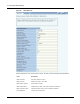
Viewing Radio Statistics Field (continued) Description Current Channel Number Current channel of operation Number of Channel Changes Number of times the channel has changed since boot-up (AP persona only) Channel Change Cause Reason the frequency changed since boot-up, if appropriate, due to user intervention or performance degradation (AP persona only) Number of Associated Stations The number of stations associated to the radio (AP persona only) Number of Trunks Number of backhaul trunks associ
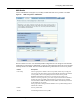
4 Configuring Radio Settings Figure 50: Radio Statistics Tab Use the pull-down list to switch between radios.
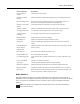
Viewing Radio Statistics Field (continued) Description Received Frame Count Count of successfully received frames (MSDUs) FCS Error Count Count of FCS errors detected when receiving a MPDU Multiple Retry Count Count of successful transmissions after more than one retransmission Retry Count Count of successful transmissions after one or more retransmission Frame Duplicate Count Count of frames received in which the Sequence Control field indicates it is a duplicate frame Acknowledgement Failure
4 Configuring Radio Settings Viewing Radio Neighbor Details A radio neighbor is a radio whose beacon frame is detected by the AP. Select Radio Neighbors from the Wireless Services menu to view summary information on all the neighboring APs within beacon range (Figure 51).
Configuring SSID Parameters Use the scrolling bars to display the full range of interfaces and data. Configuring SSID Parameters A wireless network is formed when a set of APs advertises the same value as the SSID, or network name. Figure 52 shows the Acme Works network with multiple Airgo APs, each advertising the same Corporate SSID.
4 Configuring Radio Settings SSIDs and Service Profiles A service profile consists of VLAN, COS, and minimal security attributes applied to a network or to designated classes of users once they are authenticated by a RADIUS authentication server (security portal or external authentication server). If the service profile is defined without reference to a specific user group and bound to an SSID, the profile is applied to all users who access the network.
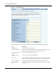
Configuring SSID Parameters SSID Table Select SSID Configuration from the Wireless Services menu to open the SSID Table (Figure 54). Figure 54: SSID Configuration - SSID Table The table lists the following information about each SSID: Field Description SSID Name Name (maximum 32 alphanumeric characters). This name is used only by the radio in AP mode and is broadcast in its beacon.
4 Configuring Radio Settings Follow these steps to rename the SSID or modify its configuration: 1 Select the checkbox for the SSID and click Modify to open the SSID Details table, which also provides access to service profiles for the SSID. 2 Enter the new SSID name. 3 Click Apply.
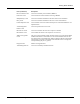
Configuring SSID Parameters SSID Details Use the SSID Details Tab (Figure 55) to modify an SSID and bind service profiles to an SSID. Figure 55: SSID Configuration - SSID Details The tab contains two areas. Use the Modify SSID Configuration area to change the current SSID configuration, as described in “SSID Table” on page 85. The bottom area shows the service profiles currently bound to the SSID.
4 Configuring Radio Settings Feature (continued) Description COS Class of service values assigned to the service profile. Security Enforcement Type of encryption required for the service profile; for user groups assigned to this service profile, the security enforcement setting supersedes the encryption type configured for the overall network.
Configuring SSID Parameters Profile Table The Profile Table tab (Figure 57) lists all the currently defined service profiles. Each service profile includes attributes for security enforcement, VLAN ID, and COS value. Binding a service profile to an SSID determines the privileges and restrictions that apply to user groups associated with the profile. NOTE: Changes made to SSID or service profiles cause affected users to be automatically disassociated from the AP.
4 Configuring Radio Settings Perform the following functions from this tab: Function Steps Add a new service profile 1 Click Add to create a new service profile. 2 Enter the profile name, which must be unique. (required) 3 Select the VLAN for the profile. 4 Enter a COS value for the profile. The range is 0-7. For more information, see “Configuring Quality of Service” on page 117. 5 Select an enforcement level for data encryption to apply to the profile.
Managing Client Stations Use the Multiple SSID tab (Figure 59) to enable the multiple SSID feature. Make a selection, and click Apply. After enabling the multiple SSID feature, additional SSIDs can be added on the SSID Table (see “SSID Table” on page 85). When multiple SSIDs are enabled on the Airgo AP, that AP no longer broadcasts an SSID in its beacon frame.
4 Configuring Radio Settings Stations The Stations tab (Figure 60) shows the client stations currently associated to the AP. Figure 60: Station Management - Stations Use this panel to control association to the Airgo AP.
Managing Client Stations Field (continued) Description Association Status Associated or reassociated to the AP Select a station from the list and click a button at the bottom of the panel to perform any of the following functions: Item Description Disassociate Detach the station from the AP and remove station related information. Link Stats Display information about the link strength and quality between the AP and station. Security Stats Display current security statistics.
4 Configuring Radio Settings Select a station from the Station Associations table and click Link Stats to display the following information: Field Description Station MAC address The MAC address that identifies the station Mode 802.
Configuring Inter Access Point Protocol (IAPP) Figure 62: Station Security Statistics Select a station from the Station Associations table and click Security Stat to display the following information: Field Description Station MAC The MAC address that identifies the client station MAC Address MAC address of the AP Auth Type Authentication used by station (Open, Shared key, EAP, or MAC-ACL) Encryption Encryption used by station (AES, TKIP, WEP, or open access) AES Transmitted Blocks Number of A
4 Configuring Radio Settings The panel contains the following tabs: • IAPP Service — Enable or disable IAPP. • Topology — View BSSID, IP address, and compatibility details. • Stats — View statistics details, including notifications sent and received, “move” notification and response details, and details on Intra-AP moves. IAPP Service Use the IAPP Service tab (Figure 63) to enable IAPP. Selecting Enable IAPP initializes IAPP to perform network discovery and communicate with other APs.
Configuring Inter Access Point Protocol (IAPP) IAPP Topology The read-only IAPP Topology tab (Figure 64) displays information about all the neighboring APs this AP has discovered, including the BSSID, IP address, and Compatibility (whether the IAPP protocol can be established with the neighboring AP).
4 Configuring Radio Settings IAPP Statistics The IAPP Stats tab (Figure 65) lists information about IAPP activity.
Performing Radio Diagnostics Item Description Move Response Failures Sent Number of move responses with a FAILURE status sent to other APs during the station reassociating process Move Response Failures Received Number of move responses with a FAILURE status received from other APs during the station reassociating process Number of Intra-AP Moves Number of successful station reassociations between APs Number of Intra-AP Moves Failures Number of unsuccessful station reassociations between APs Clic
4 Configuring Radio Settings Link Test Use the Link Test tab (Figure 66) to test connections to IP devices or run performance tests on specified links. Figure 66: Radio Diagnostics - Link Test NOTE: The Link Test graphing feature requires the installation of Sun Java (not Microsoft Java) on your Microsoft Internet-Explorer web browser. For download instructions, go to www.java.com.
Performing Radio Diagnostics To perform a link test: 1 Click Add to open the Link Test Setup entry panel (Figure 67). Figure 67: Radio Diagnostics - Link Test - Setup 2 Configure the following: Field Description Interface Select the AP radio. Station MAC Select the MAC address of the station included in the link test. Test Criteria Select whether the test is for a specified duration (seconds) or number of packets. Enter the duration in the area to the right of the Test Criteria pulldown list.
4 Configuring Radio Settings Select from the following set of link test parameters to display a graph of the test results: Item Description Downlink signal strength Strength of the signal sent from the AP to the client station (percentage) Uplink signal strength Strength of the signal sent from the client station to the AP (percentage) Downlink signal quality Quality of the signal sent from the AP to the client station (percentage) Uplink signal quality Quality of the signal sent from the client s
Performing Radio Diagnostics Walk Test CAUTION: These Radio Diagnostics are to be used only by Product Engineers. The information below is for reference only. Figure 69: Radio Diagnostics - Walk Test Parameter Parameter Description Range/Units WNI_CFG_CURRENT_TX_ANTENNA # of TX chains 1 to 2 / + WNI_CFG_CURRENT_RX_ANTENNA # of RX chains 1 to 3 / – WNI_CFG_DEFER_THRESHOLD Packet Detection Threshold 0–254 / dBm + 130 WNI_CFG_ACK_TIMEOUT_11A Ack Timeout 802.
4 Configuring Radio Settings Parameter (continued) Parameter Description Range/Units WNI_CFG_MAX_ACK_RATE_11B Max Ack Rate 802.11b MAC rate encoding: Rate - Entered Value 1-2 2-4 5.5 - 11 11 - 22 104 WNI_CFG_SHORT_PREAMBLE Enables or Disables Short Preamble DISABLE (0), ENABLE (1) WNI_CFG_CWMIN_0_11A Min Contention Window Size for 802.11a (TC0) 0 - 1023 / slots WNI_CFG_CWMIN_0_11B Min Contention Window Size for 802.
5 Configuring Networking Settings This chapter explains how to configure the advanced networking features of the Airgo Access Point.
5 Configuring Networking Settings Figure 70: Airgo Networks Wireless Network Elements Enterprise Boundry NMS RADIUS WAN Router with Firewall Internet Corporate Network 10/100 Ethernet Network Operations Center LAN Switch/Router AP with 2 Radios AP with 1 Radio 802.11a 802.11g/b AP with 1 Radio 802.11a (or 802.11g/b) 802.11g/b (or 802.
Configuring Bridging Services learned at each interface (port) of the bridge. The bridge configuration is automatic and requires no user configuration. Figure 71: Bridge Configuration - Bridge & STP Each bridge name is composed of a prefix, br, together with a bridge number. When the VLAN feature is enabled, the VLAN ID is used as the bridge number. The following IDs are reserved: • br1 represents VLAN 1 and is the default bridge for forwarding user data traffic.
5 Configuring Networking Settings The default setting for STP is Enabled. Disable STP if the network is small to mid-size and looping is not a concern. Bridge Statistics The Bridge Stats tab (Figure 72) provides a summary of transmit/receive statistics for each bridge or VLAN. The statistics are calculated from the last time the AP was rebooted or the Clear Statistics button was selected. Click Clear Statistics to return the collected values to zero and start collecting statistics again.
Configuring IP Routes Figure 73: Bridge Configuration - ARP Table Configuring IP Routes IP routing expands the addressing capability of the Airgo AP and allows you to mange the AP from outside its local subnet. Use the IP Routing panel (Figure 74) to explicitly address subnets that are not local. If a destination subnet is not entered into this panel, then default network routing applies.
5 Configuring Networking Settings 110 Field Description Gateway IP Enter the IP address of the gateway that will route traffic between this AP and the destination subnet. Interface Name Enter the name of the bridging interface. Use the br prefix, as described in “Configuring Bridging Services” on page 106.
Configuring VLANs Configuring VLANs VLANs are key to helping enterprises improve network traffic flow, increase load, and deliver varying levels of service and access to different groups of users. For example, Figure 75 shows how Acme Works uses two VLANs: one for normal corporate traffic and one for Finance Department traffic.
5 Configuring Networking Settings VLAN Table Choose VLAN from the Networking Services menu to list information about each VLAN and interface (Figure 76). Figure 76: VLAN Configuration - VLAN Table The VLAN table contains the following columns of information: 112 Field Description VLAN ID Numeric identifier for the VLAN. In bridging notation, this is the numeric ID that follows the br prefix. Name Alphanumeric name of the VLAN. The field is optional, unless it is the default VLAN.
Configuring VLANs Field Description Tagged Indication of whether the identity of the VLAN is explicitly encoded in transmitted packets. Each frame contains a 4-byte tag that encodes the VLAN to which the packet belongs when it is sent on a tagged interface. If the received packet is untagged, the packet is classified as belonging to the interface VLAN. If the VLAN interface is not tagged, then the AP drops any VLAN-tagged packet. When the packet is transmitted from the interface, it is untagged.
5 Configuring Networking Settings Interface VLAN When the AP receives a frame, it must determine the VLAN to which the frame belongs. If the received frame is tagged, then VLAN is already known and the AP can route the packet accordingly. The Interface VLAN tab (Figure 78) specifies treatment of frames that arrive at the AP in an untagged state. Each interface is assigned to a VLAN, which then receives all untagged frames arriving at the interface.
Configuring VLANs Field Description VLAN Name Alphanumeric name of the VLAN IP Address Address used to access the VLAN MAC Address MAC addresses of the client stations mapped to this VLAN through their user group’s service profile See “Configuring SSID Parameters” on page 83 for information on service profiles.
5 Configuring Networking Settings VLAN Statistics The VLAN Stats tab (Figure 80) provides a summary of transmit/receive statistics for each VLAN. The statistics are calculated from the last time that the AP was rebooted or the Clear Statistics button was selected. Click Refresh to update the statistics or Clear Statistics to return the collected values to zero and start collecting statistics again.
Configuring Quality of Service Configuring Quality of Service Under normal network conditions, traffic in the wireless network is routed on a best-effort basis, and all types of traffic are treated with equal priority. Quality of Service (QoS) permits priority setting for different types of traffic, which can be important for applications in which even minor interruptions in packet transmission can have a deleterious effect on perceived results. Examples include streaming media or Voice-over-IP (VoIP).
5 Configuring Networking Settings Rule (continued) Description DiffServ Code point (DSCP)-to-COS Defines a mapping based on the first 6 bits in the ToS byte of the IP header. Incoming packets that have a DSCP value can be mapped to COS. IP Protocol Assigns COS value based on the standard numbers for individual IP protocols. Class Order Determines the order in which all the COS mapping rules are applied. Use the QoS Configuration panel to define TCID, VLAN, and Interface COS mappings.
Configuring Quality of Service Ingress QoS Use the Ingress QoS tab to assign COS values to incoming 802.11 packets. If a packet has a COS value in the VLAN tag when it arrives at the AP, its COS value is honored by the AP. If the packet is not VLAN-tagged, it can be classified at the ingress interface by way of a COS map defined on the Ingress QoS tab (Figure 82).
5 Configuring Networking Settings Perform the following functions on this tab: Function Steps Define TCI- to-COS mapping 1 Select the radio interface for the mapping. 2 Select a COS value for each TCID value, or select Default to accept the default mapping. 3 Click Apply. Define VLAN-to-COS mapping 1 Click Add. 2 Select the AP interface. 3 Select the VLAN ID. (See “Configuring VLANs” on page 111 for information on VLAN IDs.) 4 Select a COS value or select Default to use the default mapping.
Configuring Advanced QoS Configure the following fields on this tab: Field Description Select Egress Radio Interface Select the AP interface. Default Select to use the default mapping. COS Displays the COS levels. TCID If Default is not selected, map each COS level to a TCID level. Click Apply to save your changes or Reset to return to previously saved values. QoS Stats The QoS Stats tab (Figure 85) presents incoming packet and outgoing packet counts for each of the AP interfaces.
5 Configuring Networking Settings Class Order The COS mappings on the QoS and Advanced QoS Configuration panels may yield conflicting results for ingress packet priority. Use the Class Order tab (Figure 85) to specify the order in which to apply each of the rules. When a packet arrives at the AP, the AP checks to see whether a mapping exists for the first rule in the class order list. If so, that mapping is applied to the packet. If not, the AP checks whether a mapping exists for the second rule.
Configuring Advanced QoS Field Description Current Ingress Class Order Displays the current setting for class order. Ingress Class Order Default Select to use the default mapping. Ingress Class Order Move to Top If the default order is not chosen, select the class that you want to have at the top of thc class order list, and click Add. This adds the class to the Selected Classes list. Continue adding classes in the order you want them to be applied. When you have finished, click Apply.
5 Configuring Networking Settings Figure 86: Advanced QoS Configuration - IP DSCP Configure the following fields on this tab: 124 Field Description Select Interface Select the AP interface. Default Select to use the default mapping.
Configuring Advanced QoS Field Description DSCP String If Default is not chosen, enter up to eight DSCP values that you want to map to a specific COS value. COS Select the COS value. Click Apply to save all the changes on the tab. IP Protocol Use the IP Protocol tab (Figure 87) to base the COS mapping on IP protocol numbers, as defined in Version 4 of the IP protocol. Current protocol number assignments are available at http:// www.iana.org/numbers.html.
5 Configuring Networking Settings IP Precedence Use the IP Precedence tab (Figure 88) to base the COS mapping on the first 3 bits in the ToS byte of the IP header. Figure 88: Advanced QoS Configuration - IP Precedence Configure the following fields to define an IP Precedence-to-COS map: Field Description Select Radio Interface Select the AP interface. Default Select to apply the default mapping COS If Default is not chosen, select the desired COS values.
Configuring Packet Filters Figure 89: Filter Configuration - Filter Table From the Filter Table tab, add a new filter by clicking Add, or edit an existing one by selecting the filter and clicking Edit. The Add Filter Entry panel opens (Figure 90). Enter or select values for the following fields: Field Description Interface Name If creating a new filter, select an interface from the pull-down list.
5 Configuring Networking Settings Figure 90: Filter Configuration - Add Filter Entry Panel Filter Statistics The Filter Stats tab (Figure 91) lists statistics for each defined filter. The statistics are calculated from the last time the AP was rebooted or the Clear Statistics button was selected. The Hits column shows the number of packets of the specified type received on the interface with the defined filter.
Configuring Interfaces Interface Table Choose Interface from the Networking Services menu to open the Interface Table (Figure 92). Use this tab to assign an IP address to each interface, thereby making it possible to route traffic to the interface. Without an assigned IP address, traffic can only be bridged to the interface, not routed.
5 Configuring Networking Settings Use the Encapsulation Configuration section at the bottom of the tab to ensure that the AP can operate with older equipment that is not fully 802.11-compatible. 802.1h is the current standard for encapsulation. For other, incompatible equipment, select Encapsulated to encase the Ethernet frames from the equipment within standard 802.11 frames. Click Apply after making any change.
Ping Test Figure 94: SNMP Configuration Enter values in the following fields to define the basic SNMP configuration: Field Description Community String Enter the alphanumeric community string. (required) Community Read/Write Status Indicate the read or read/write status of the community. Trap Sink IP Address Enter the IP address where SNMP traps should be sent. (required) Trap Community Enter the community for SNMP traps. Trap Sink Port Indicate the port identified for the SNMP traps.
5 Configuring Networking Settings Figure 95: 132 Ping Test Installation and User Guide: Airgo Access Point
6 Configuring a Wireless Backhaul This chapter explains how to set up a wireless distribution system to cover a large area with limited wired network connectivity.
6 Configuring a Wireless Backhaul ports on radios, and bridging functions such as address learning, packet forwarding, and spanning tree protocol (STP). Use of Radios for Backhaul Each access point in a backhaul configuration must have two radios and be enrolled in the network.1 Typically, one of the radios operates in normal (AP) mode to serve downstream access point radios or laptop clients.
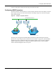
Use of Radios for Backhaul Figure 98: Frequency Bands and Hops in Wireless Backhaul Networks Root AP: 2.4 and 5 GHz First hop: 5 GHz Second hop: 2.4 GHz Good for legacy clients 5 GHz A0059 The alternating band requirement carries implications for the number of backhaul hops that may be desired to support network clients.
6 Configuring a Wireless Backhaul Wireless Backhaul Security By implementing a common security policy across the network, you can provide appropriate security to clients while also ensuring that incompatibilities do not prevent formation of wireless backhaul links. Overall wireless backhaul security depends upon the security modes assigned to all the AP and BP radios in the backhaul arrangement.
Wireless Backhaul Security be sure that all APs are configured with identical SSID and PSK-password. This is necessary because PSK-password is bound to the SSID. A BP radio in a wireless backhaul network uses the PSK-password tied to the SSID to authenticate with an uplink AP. Even if you configure the BP backhaul criteria to include the correct uplink AP SSID, it will not form a backhaul if the SSID on the downlink AP is different from that of the uplink AP.
6 Configuring a Wireless Backhaul Non-Wired or “Pseudo-Wired” Backhaul Configurations It is possible to configure a wireless backhaul to operate without a working connection to a wired network. This approach may be useful in a warehouse or factory setting as a means of establishing a wireless network disconnected from the corporate infrastructure.
Setting Up a Wireless Backhaul Figure 100: Backhaul Configuration - Link Criteria Installation and User Guide: Airgo Access Point 139
6 Configuring a Wireless Backhaul The Uplink Configuration settings on this tab restrict how the backhaul is configured. Select some or all of the settings, or leave this section blank to permit unrestricted choice of uplinks: Field Description Select Radio Interface Select radio wlan0 or wlan1. Backhaul Security Select from the following options (see “Wireless Backhaul Security” on page 136 for more information): • Open-or-WEP: Compatible with the WEP or Open global security mode.
Setting Up a Wireless Backhaul Use the area at the bottom of the tab to specify the BSSID criteria (in conjunction with the Uplink BSSID buttons): Field Description Add BSSID To add BSSIDs to the Selected list, add from the pull-down list, and click Add. Alternatively, enter the name of a BSSID, and click Add. The saved BSSIDs are displayed in the selected BSSIDs list on the right.
6 Configuring a Wireless Backhaul Figure 102: Backhaul Configuration - Trunk Table This tab contains the following information: Feature Description Interface Name Radio interface of the BP radio (uplink) or AP radio (downlink) to which downlink trunks are connected. Applies to uplink and downlink trunks. Band (2.4GHz or 5GHz, or both) Operating band of the uplink or downlink trunks. Applies to uplink and downlink trunks. For the uplink trunk the band is the operating band of the BP radio.
Setting Up a Wireless Backhaul Figure 103: Backhaul Configuration - Trunk Stats This tab contains the following information: Field Description Interface The AP radio interface (wlan0 or wlan1) Rx Bytes Number of bytes received at this AP Rx Packets Number of packets received at this AP Tx Bytes Number of packets transmitted by this AP Tx Packets Number of packets transmitted by this AP Rx Multicast Packets Number of multicast packets received by this AP Click Clear Statistics to return the
6 Configuring a Wireless Backhaul 144 Installation and User Guide: Airgo Access Point
7 Managing Security This chapter describes the encryption and authentication features of the Airgo Access Point and explains how to set the security configuration.
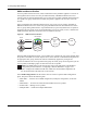
7 Managing Security Figure 104: Wireless Security Elements Users Security Guest Security ¥ All WPA Modes ¥ EAP-TLS, -PEAP, -PSK ¥ AES, TKIP, or WEP Encryption ¥ Password or Custom Access Control ¥ Guest-VLAN for Internet Access ¥ Session Management Guest Security User Security Admin Security AP Security AP Security Admin Security ¥ Secure AP Enrollment ¥ Batch or One-Click ¥ Certificates & Password ¥ Admin & Operator ¥ Username, Password ¥ SSH, HTTPS, SNMPv3 A0047 Security Elements Each security
Data Encryption User Security Acceptable and effective solutions for user authentication depend upon the network size, complexity, and existing authentication infrastructure. Current user authentication standards are based on the IEEE 802.1x specification, which identifies users and permits connectivity based upon policies established in a central server.
7 Managing Security Open encryption provides no protection, and is only recommended when security is not of concern. WPA-AES is recommended for all installations, if possible.
Zone Privacy VLANs. A VLAN switch is able to segregate traffic between the two VLANs such that any client of the first AP is not able to contact any client on the second AP. To provide full connectivity between APs for management traffic, assign all ports on the APs to the management VLAN. Zone Privacy Deployment without VLANs When zone privacy is implemented without VLANs, communication forwarding rules can affect station and management traffic between the APs.
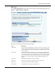
7 Managing Security Figure 106: Zone Privacy - using a Management VLAN “root” AP Management VLAN Non-management VLAN Configuring Wireless Security Choose Wireless Security from the Security Services menu to configure the protocols for data encryption and user authentication. The Wireless Security panel contains two tabs: • Security Mode — Configure WPA, WEP, or open encryption and authentication. • SSID Auth — Configure security settings for the SSID.
Configuring Wireless Security Figure 107: Security Services - Security Mode WPA Security Select Enable WPA to activate the WPA authentication and encryption fields. The following options are available: Field Description WPA Security Mode WPA-EAP — For RADIUS-based networking keying WPA-PSK — For pre-shared keys Encryption Type AES, TKIP, AES, and TKIP Click Apply to save the configuration, or Reset to return to the previously saved values.
7 Managing Security NOTE: Selecting WPA-EAP or WPA-PSK displays a link that leads to the SSID Authentication tab. Refer to “SSID Authentication” on page 152 for instructions on using this tab. WEP Security If it is necessary to configure WEP security, select Enable WEP to activate the WEP fields. Configure the following values in the WEP security area: Field Description Enable WEP Activate the WEP settings. The Airgo AP supports WEP with dynamic and manually entered keys.
Configuring Wireless Security Figure 108: Security Services - SSID Auth Assign the following values to configure SSID authentication: Feature Description SSID Name Select from the SSID pull-down list. Click SSID Details to view more SSIDrelated information, enable multiple SSIDs, or change other SSID attributes. WPA Pre-Shared Key Enter the pre-shared key for WPA, if appropriate. This field is grayed out if WPA-PSK is not the selected authentication type.
7 Managing Security If an external RADIUS server is to be used for MAC address based ACL lookups, the following apply: 1 The RADIUS server must have PAP authentication enabled for these MAC ACL users 2 The RADIUS server can expect the AP to send the following standard RADIUS attributes in the authentication request for purposes of policy configuration and interoperability.
Configuring Authentication Zones 4 The RADIUS server may optionally send back an attribute encoded with the user group. Configuring Authentication Zones RADIUS servers may be used to authenticate wireless users and administrative users, and to check MAC Access Control Lists for the SSID. Select Authentication Zones from the Security Services menu to define zones for RADIUS authentication and to add external RADIUS servers to the list of available authentication servers.
7 Managing Security Figure 110: Authentication Zones - Add Auth Zones To add a new authentication server, click Add Auth-Server, and enter the following values for each new RADIUS server: Field Description Auth Server IP address of the RADIUS authentication server Shared Secret Secret key to be entered and confirmed Port Number Port number for the server (default is 1812) Click Add to save the values, or click Reset to clear the fields on the panel.
Configuring Administrator Security Configuring Administrator Security Use the Administrator Security menu item to administer the administrator password and view AP certification information. Administrator Password Choose Administrator Security from the Security Services menu to open the Administrator Security panel, Admin Password tab (Figure 112).
7 Managing Security • The external RADIUS server must have Password Authentication Protocol (PAP) authentication enabled for administrative users. • The Airgo AP sends a standard RADIUS attribute called Service-Type in the authentication request. The value of this attribute is set to Administrative to indicate that the user to be authenticated has requested access to an administrative interface on the AP.
Viewing Security Statistics Viewing Security Statistics Choose Security Statistics from the menu tree to open the Security Statistics panels. This panel contains the following tabs: • Authenticator Stats — View authentication statistics for each selected AP radio. • Supplicant Stats (Supplicant Statistics) — View statistics on 802.1x requests for each selected BP radio. • Auth Diag — View authentication diagnostics statistics, including backend data.
7 Managing Security Field Description Last RX EAPOL Frame Version The EAPOL version from the last EAPOL frame received by the AP. RX EAPOL The total number of EAPOL frames received by the AP. RX EAPOL-Start The total number of EAPOL-Start frames received by the AP. This count increments as stations or BPs request the AP to start their authentication sequence. RX EAPOL-Logoff The total number of EAPOL-Logoff frames received by the AP. This count may not increment as most 802.
Viewing Security Statistics Figure 115: Security Statistics - Supplicant Stats The tab contains the following information: Field Description Interface Select the radio interface of interest for viewing statistics. Last RX EAPOL Frame Source The source MAC address from the last EAPOL frame received by the BP. This identifies the upstream AP that is currently authenticating or reauthenticating with the BP. Last RX EAPOL Frame Version The EAPOL version from the last EAPOL frame received by the BP.
7 Managing Security Field Description TX EAPOL The total number of EAPOL frames transmitted by this BP. TX EAPOL-Start The total number of EAPOL-Start frames transmitted by the BP. This count goes up as the BP requests the AP to start its authentication sequence. TX EAPOL-Logoff The total number of EAPOL-Logoff frames transmitted by the BP. This count will not increment as the BP does not send this 8021.x frame for security reasons.
Configuring Advanced Parameters Field Description Auth Successes The total number of RADIUS authentication packets that contained an ACCESS-ACCEPT. These are sent by the RADIUS server when the authentication sequence succeeds. Auth Failures The total number of RADIUS authentication packets that contained an ACCESS-REJECT. These are sent by the RADIUS server when the authentication sequence fails.
7 Managing Security Field Description RADIUS Retries Number of retransmit attempts after which the RADIUS request is marked a failure. External RADIUS Group-Key Attribute (for User Group ID) RADIUS attribute used by the AP to determine the user group (see “SSID Details” on page 87). When a wireless user is authenticated by a RADIUS server, the server can optionally send the AP the user group for the association.
Configuring Zone Privacy The panel contains the following settings: Item Description Enable Zone Privacy Allows you to enable zone privacy on one or more VLANs. 1 Select a VLAN to which zone privacy will apply or select All VLANs to apply the feature across all defined VLANS. 2 Click Enable. 3 Repeat if desired to enable zone privacy on additional VLANs. Zone Privacy Table Displays a list of VLANs and their current zone privacy status.
7 Managing Security 166 Installation and User Guide: Airgo Access Point
8 Configuring Guest Access This chapter describes how to enable guest user access to the wireless network while protecting the network from unauthorized use. It contains the following sections: • • • • • Overview Internal Landing Page External Landing Page Configuring Guest Access with VLANs Guest Access Services Panel Overview Guest access allows visitors to a facility to access the Internet through the wireless network without gaining access to the corporate network.