Sparrow Mk4 ROOF TOP AIR CONDITIONER Model Number: 5860001 Serial Number: Date Purchased: WARNING It is important that this installation manual is properly read and understood before installation. The unit must be installed by a qualified service technician. Failure to properly install the unit or attempting to modify it in any way can be extremely hazardous and may result in property damage and personal injury.
Sparrow MK4 General Information I. PURPOSE III. CONDENSATION The Aircommand Sparrow air conditioning unit is designed for installation on the roof of a caravan or recreation vehicle to provide reverse cycle heating and cooling. In areas of high humidity, the humid air within the van will cause “sweating” or condensation in parts of the unit as the humid, warm air contacts the colder air discharge system.
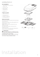
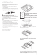
Installation Parts List MAIN COMPONENTS 1 Sparrow Mk4 rooftop air conditioner 1 2 Weather collar 3 Black plastic duct 4 Brace assembly 5 Plenum filters x 2 6 Plenum cover 2 FITTINGS & FIXTURES 7 M8x120mm bolts x 4 8 Hold down bars x 4 3 9 Plenum cover screws x 4 10 Self tapping screws x 6 4 BEFORE INSTALLATION Ensure that the installation instructions have been properly read and understood. 5 Installation must confirm to nation wiring regulations and in particular AS3001 – 2008.
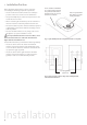
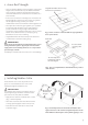
1. Installation Position Before beginning, mark out the position of the unit considering the following important requirements: • The air conditioner should be situated as centrally as possible on the van, to ensure even air distribution. There should be a minimum of 100mm clearance around the perimeter of the unit to allow for service access and air flow to condenser. Hot air is ejected from this exhaust; consider nearby roof hatch.
2. Assess Roof Strength • The roof members MUST be strong enough to support the weight of the unit without any roof deflection that will cause “pooling” of water around the unit. Contact your caravan manufacturer to confirm the max load the roof is able to handle. Longitudinals must be fixed securely to transverse roof members • If the roof does not have an existing hole one must be cut. Cut through the roof then use the roof hole as a guide to cut through the ceiling.
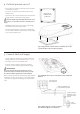
4. Position Sparrow on roof • Remove the air conditioner from the carton and move to installation position. • Put a circle of sealant around each bolt hole in the weather collar. Apply circle of sealant around 4 bolt holes. • Position the unit over the weather collar. The unit will engage with the collar and self-align (Fig 6). The unit weights approximately 28kg. Ensure a two person lift or use a mechanical hoist to avoid the risk of injury.
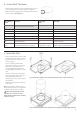
6. Assess Roof Thickness • Measure the roof thickness and consult the table across to check if adjustments to the duct length are required. • NOTE: If the duct length needs to be adjusted then cut the excess from the un-notched end. Roof thickness (mm) Comment Duct length (mm) Bolt length 25 Absolute minimum – ring must be removed from top of plenum ducting.
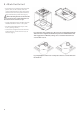
. Attach Duct to Unit • Raise the brace assembly and slip the black plastic duct over the outside of the fan outlet underneath the rooftop unit. Ensure that the notch cut in the plastic ductwork aligns with the fans power cable (Fig 12). When attaching the duct to the unit take care to ensure it forms a tight, unbroken seal that doesn’t allow cold air to escape. • Engage and tighten the four M8 bolts with the threaded inserts in the rooftop unit. • Recommended tightening torque of the bolts is 7 N.m (5.
. Attach Plenum Cover Connect the main cover of the plenum to the duct by attaching the blue suspension cord to the lug on the inside of the cover (Fig 13). • This will allow you to use two hands to connect the control cable (Fig 14). • Connect the key pad control cables together (see below). Be sure that the plug joins the corresponding wire colours together (yellow to yellow, red to red etc). Failure to properly plug the control cables together correctly will result in loss of power to display.
Commissioning of the Unit 1. Turn the power on at the circuit breaker. 2. Press the ON/OFF button and press the MODE button to select FAN. 3. Cycle through the LOW, MED and HIGH fan speeds checking that all speeds run. 4. Set mode to COOL, adjust temperature via up/down buttons to 4˚C below the display temp (ie room temp) compressor will start within three minutes. 5. Set mode to HEAT, similarly set temperature to 4˚C above the display temperature. Compressor will start within three minutes.
General Specifications Air conditioner Air discharge plenum height width 205mm 560mm length 975mm weight 26.6kg height 65mm width 535mm length 555mm weight 2.4kg Model number 5860001 Electrical rating 240V, 50Hz Refrigerant 407C, 450g Rated capacity cooling 2000W heating 2150W cooling 920W heating 930W cooling 3.9A heating 4.0A Power input Rated current Max input 1020W Max current 4.
Spare Parts REFERENCE DESCRIPTION 1 5862022 Top housing fitting kit 2 5862001 Top housing 3 5862033 Bottom housing 4 5862015 Inside fan EPS housing 5 5861010 Outside fan assembly 6 Refer to Aircommand service 7 5861006 Electrical kit 8 5862010 Inside fan assembly 9 5861002 Consensate collector set 10 5861001 Weather collar assembly 11 8001012 Circullar duct 12 8002031 Combined duct & brace 13 8002037 Installation fittings kit 14 5852006 Sparrow plenum assembly 15
Schematic Wiring Diagram 13
Troubleshooting It is important that any work performed on this unit is carried out by a qualified service technician. Work by an unqualified technician can be extremely hazardous and may result in property damage and/or personal injury. When attempting to diagnose a fault through our service department please have the answers to as many of the following questions as possible: This Aircommand air conditioner will display an error code on the control panel when it senses a fault.
Operating instructions Turn the unit on by pressing the ON/OFF button once. Press the MODE button to cycle through options COOL, DRY, HEAT and FAN. To select cooling, cycle mode button to highlight COOL. SLEEP MODE: lf the unit is operating in COOL mode and the SLEEP button is pressed to highlight the Sleep light, then the unit over the next one hour will automatically raise the set point by 1oC. Conversely in HEAT mode, the setpoint will be lowered 1oC.
Contact details AIRCOMMAND AUSTRALIA 954 Port Road Albert Park South Australia 5014 Australia Phone: (+61) 8 8345 8444 Fax: (+61) 8 8243 0628 AIRCOMMAND EUROPE Locke Leisure Products The Gables, Stoneleigh Road Bubbenhall Coventry CV8 3BT United Kingdom Phone: (+44) 2476 303 380 For sales enquiries please email: sales@aircommand.com.au For warranty, service or technical enquiries please email: service@aircommand.com.au For spare parts enquiries please email: parts@aircommand.com.