
User's Handbook


12
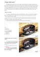
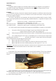
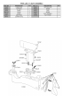
Moving the pillar on the trigger bar.
Loosening screw ‘A’ with the
1.5mm Allen key (supplied) will allow
the trigger pillar to be moved forwards
and backwards along the trigger bar. (Fig
22).
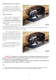
Trigger adjustment.
The operation of the trigger is con-
trolled by 3 screws C, D & E (fig 23).
The weight of pull adjustment is
controlled by screw ‘E’, and is located in
front of the trigger, housed in the trigger
guard (fig 20).
Clockwise rotation will increase the
pull weight and counter-clockwise will
decrease the weight. If the screw is over adjusted in the clockwise direction the spring will become
coil-bound and may prevent operation of the trigger.
The first stage adjuster ‘D’ is the
first screw in the trigger bar looking from
the front of the gun (fig 23). This screw
determines the length of first stage travel
before the second stage engages. Clock-
wise adjustment reduces the first stage
travel.
The second stage adjuster ‘C’ is
located next to the first stage screw (fig
23). This screw determines the exact
pull-off point of the trigger.
WARNING. Adjustment of a two-stage trigger can be difficult and should be left to experi-
enced and trained technicians. Adjustment to any one of the screws will have a direct effect on
the other two screws and could make the gun unsafe.
If you have no experience of adjusting a two-stage trigger it is highly recommended that you
seek guidance or leave the trigger on the factory settings.
Tip.
When adjusting the trigger write down on a piece of paper the number of turns and direction of
each adjuster screw. This will make it easier to recover the original settings if required.