834168 C P0811JZ IS SERIES Commercial & Security Video Intercom system INSTALLATION MANUAL Thank you for selecting Aiphone for your communication and security needs. Please read this manual carefully before installation, and keep it in a safe place for future reference. Also read the SETTING MANUAL and OPERATION MANUAL on the bundled CD-ROM. When the installation is completed, configure the system by following the SETTING MANUAL. Otherwise, the system will be nonfunctional.
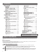
CONTENTS PRECAUTIONS ................................ 3 WARNING .......................................3 CAUTION ........................................3 GENERAL PRECAUTIONS ............3 Notes on using this system ..........4 Notices ............................................4 SYSTEM CONFIGURATIONS.......... 4 Entire system ................................4 System configuration examples ....5 ■ Standard (IP) system............................ 5 CONNECTIONS ..............................
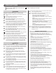
PRECAUTIONS General Prohibitions Prohibition to Dismantle the Unit Prohibition on Subjecting the Unit to Water General Precautions WARNING Negligence could result in death or serious injury. 1. Do not dismantle or alter the unit. Fire or electric shock could result. 2. Keep the unit away from water or any other liquid. Fire or electric shock could result. 3. High voltage is present internally. Do not open the case. Electric shock could result. 4. The unit is not of explosion-proof.
• Notes on using this system • • The ID/Password to access the web server for setting the system is the customer's responsibility. Make sure you set a password that cannot be easily guessed by a third party. We recommend that you change the ID/Password on a regular basis.
System configuration examples ■ Standard (IP) system The following is an example of standard (IP) system for controlling security and communication for facilities. • • • • A site must be configured with an IP-based system. A standard (IP) system can consist of local systems and IP units. A local system (Hard wired network system) without connecting to an IP network can also be an independent system. When using a local system as an independent system, it needs at least one central control unit (IS-CCU).
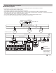
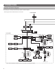
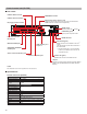
CONNECTIONS System connection diagram The following is an example of standard (IP) system connection diagram. * Refer to page 9 to 26 for details about each unit connection. To Internet/WAN Broadband router PBX / Telephone Switch (Hub) *1 IP IS-IPC IS-PU-UL or IS-PU-S Local system IS-MV (Max. 1) IS-CCU Timer (Max. 4) Monitor Recorder CD player IS-PU-UL or IS-PU-S IS-DV/IS-DVF /IS-SS PT AC transformer IS-RS (Max.
: IS system product IP : IP unit Telephone network LAN (IP network) Switch (Hub) Switch (Hub) IS-IPMV IP IS-IPDV /IS-IPDVF IP IP PS-2420/D/UL/S*2 IS-IPC*1 IS-PU-UL IP PC master station (IS-SOFT) Switch (Hub) PBX / Telephone Switch (Hub) or Local system IS-PU-S PS-2420/D/UL/S*2 or or PoE PoE (Max. 1) IS-RCU PA amplifier PA speaker IS-PU-UL or PT AC transformer Recorder IS-SS (Max.
Cables Cables and connectors are not included with the products. Refer to page 9 to 26 for details about each unit connection. Notes on cables • Unless otherwise noted, never use individual conductors, twisted pair cable or coaxial cable. • Odd number cables, such as three conductor wire, cannot be used. Notes on CAT5e/6 cables • Do not bend the cables to an extent where the radius is less than 25 mm (1”). Communication failure could result.
UNIT DETAILS Control unit common information * The information on this page is common to Central control unit (IS-CCU), Add-on control unit (IS-SCU), Room sub control unit (IS- RCU) and IP control unit (IS-IPC).
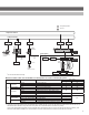
Central control unit (IS-CCU) ■ Part names CONTACT INPUT terminals CHIME INPUT terminals CONTACT OUTPUT terminals External chime source volume 1 and 2 Adjust the volume of the input source (for chime) connected to the CHIME INPUT B1 and B2 terminals respectively. PA (Paging) OUTPUT terminals POWER switch Turns the power ON ( ) or OFF ( ). POWER LED (green) Lights up when the power is ON.
■ Connections Chime input (50mVrms, 600Ω) Contact output *8 (Electric door strike, strobe light, etc.) PA output (50mVrms, 600Ω) Contact input *9 PA amplifier Sensor, etc. External sound source such as CD player, etc. *6 *2 *1 NP 2C φ0.65-1.2mm (22-16 AWG) 15m (50') NP NP 2C φ0.65-1.2mm (22-16 AWG) 2C φ0.65-1.2mm (22-16 AWG) P NP 2C φ0.65-1.2mm (22-16 AWG) 15m (50') 2C φ0.65-1.2mm (22-16 AWG) *3 *7 Monitor 1, Recorder 1 Monitor 2, Recorder 2 BNC connector BNC connector 2C φ0.65-1.
Add-on control unit (IS-SCU) ■ Part names CONTACT OUTPUT terminals PA (Paging) OUTPUT terminals POWER switch Turns the power ON ( ) or OFF ( ). POWER LED (green) Lights up when the power is ON. POWER terminals MASTER STATION ports VIDEO/AUDIO DOOR/SUB STATION ports ID setting switch (→P.13) Central control unit (IS-CCU) ports STATUS LED (green) Blinks when this unit is initialized or an error*1 occurs. The LED will light up when this unit returns to the normal state.
■ Connections Contact output *4 (Electric door strike, strobe light, etc.) PA output (50mVrms, 600Ω) Monitor 1, Recorder 1 PA amplifier NP 2C φ0.65-1.2mm (22-16 AWG) 15m (50') BNC connector BNC connector *1 NP Monitor 2, Recorder 2 NP 2C φ0.65-1.2mm (22-16 AWG) AC transformer PT 2C φ0.65-1.2mm (22-16 AWG) Coax 15m (50') NTSC Coax 15m (50') NTSC BNC connector P1 P2 P3 P4 L1 L2 L3 L4 V1 MASTER STATION NP: Non-polarized P: Polarized V2 VIDEO OUTPUT CONTACT OUTPUT (AC/DC24V 0.
Room sub control unit (IS-RCU) ■ Part names CONTACT OUTPUT terminals PA (Paging) OUTPUT terminals POWER switch Turns the power ON ( ) or OFF ( ). POWER LED (green) Lights up when the power is ON. POWER terminals AUDIO DOOR/SUB STATION ports Central control unit (IS-CCU) / IP control unit (IS-IPC) ports ID setting switch (→P.15) STATUS LED (green) Blinks when this unit is initialized or an error*1 occurs. The LED will light up when this unit returns to the normal state.
■ Connections Contact output *4 (Electric door strike, strobe light, etc.) PA output (50mVrms, 600Ω) PA amplifier *1 NP NP NP 2C φ0.65-1.2mm (22-16 AWG) 15m (50') 2C φ0.65-1.2mm (22-16 AWG) AC transformer PT 2C φ0.65-1.2mm (22-16 AWG) NP: Non-polarized P: Polarized ID setting switch *3 P1 P2 P3 P4 L1 L2 L3 L4 CONTACT OUTPUT (AC/DC24V 0.
IP control unit (IS-IPC) IP This unit is needed to connect a local system to a standard (IP) system. ■ Part names CO port (Telephone) LAN port POWER switch Turns the power ON ( ) or OFF ( ). POWER LED (green) Lights up when the power is ON. POWER terminals Central control unit (IS-CCU) / Room sub control unit (IS-RCU) ports STATUS LED (green) Blinks when this unit is initialized or an error*1 occurs. The LED will light up when this unit returns to the normal state.
■ Connections PBX/Telephone (North America only) Switch (Hub) 10BASE-T 100BASE-TX 100m (330') CO LAN TELEPHONE ETHERNET IS-CCU IS-RCU IP1 IP2 DC48V IP3 IS-CCU IS-RCU P: Polarized P IP1 IP2 IP3 2C φ0.8-1.
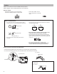
Color monitor master station (IS-MV) * For the part names and their functions, see the OPERATION MANUAL. ■ Accessories Mounting bracket × 1 Desktop stand × 1 Tie-wrap × 1 Name plate × 1 Name card × 1 Screw (15mm (5/8"), for wall-mounting) × 4 Screw (25mm (1"), for gang box) × 4 Screw (10mm (7/16"), for desktop stand) × 4 China RoHS paper × 1 ■ Mounting When mounting on a wall Name card × 1 (included*1) 3 Mount the unit on the mounting bracket.
When mounting on a desktop stand 4 1 Mount the unit on the mounting bracket. 2 Set up the desktop stand. * Set up the desktop stand on a level surface etc. so that it is stabilized. Fix the desktop stand in place if needed. * The desktop stand allows you to adjust it in 3 setup angles. Put the leg in a groove on the base that corresponds to the desired angle. Fasten the mounting bracket to the desktop stand.
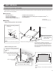
Vandal-resistant video door station (IS-DV, IS-DVF), Vandal-resistant audio door station (IS-SS) ■ Accessories Screw (for wall-mounting) × 4 (IS-DV only) Anchor × 4 (IS-DV only) Transparent name plate × 2 (IS-DV and IS-DVF only) Special screw × 4 (IS-DVF and IS-SS only) Special screwdriver × 1 Back box × 1 (IS-DVF and IS-SS only) China RoHS paper × 1 ■ Mounting locations (IS-DV and IS-DVF) Do not install this unit in any of the following locations where lighting or the ambient environment could impact the
■ Mounting IS-DV (surface-mount) Loosen the screw with the special screwdriver, and remove the front panel. NOTE Make room for threading a screw. * Use board anchors or concrete Screw mounting hole x 4 plugs as needed. Anchor x 4 (included) Vandal-resistant front panel Ø 6 mm (Ø 1/4") 35 mm (1-3/8") Unit center Option wires Mounting height GL=1,500 mm (5') Loosen Special screwdriver (included) Unit center 194 mm (7-11/16'') 1 Fasten the unit to the mounting surface.
■ Connections (IS-DV and IS-DVF) CAT5e/6 (non-shielded) Electric door strike *1 D D4 D1 300m (980') (Select one port.) Central control unit (IS-CCU) NC COM NO or φ0.65-1.2mm (22-16 AWG) 10m (33') CAT5e/6 (non-shielded) D1 300m (980') AC transformer D8 (Select one port.) Add-on control unit (IS-SCU) PT φ0.65-1.2mm (22-16 AWG) 10m (33') φ0.65-1.2mm (22-16 AWG) 10m (33') Option Inlet wires * Connect to the electric door strike according to its specifications.
■ Connections (IS-SS) CAT5e/6 (non-shielded) Electric door strike *1 D D1 300m (980') D4 (Select one port.) Central control unit (IS-CCU) NC COM NO or φ0.65-1.2mm (22-16 AWG) 10m (33') CAT5e/6 (non-shielded) D8 D1 300m (980') AC transformer (Select one port.) Add-on control unit (IS-SCU) PT φ0.65-1.2mm (22-16 AWG) 10m (33') or CAT5e/6 (non-shielded) C1 φ0.65-1.2mm (22-16 AWG) 300m (980') 10m (33') C30 (Select one port.
Room sub station (IS-RS) ■ Accessories Mounting bracket × 1 Screw (for wall-mounting) × 2 Tie-wrap × 1 Screw (for gang box) × 2 China RoHS paper × 1 ■ Mounting CAT5e/6 cable 1-gang box The unit 3 Mount the unit on the mounting bracket. 1 Option wires Fasten the mounting bracket to the wall. Mounting bracket (attached to the unit with shipment) Screw (for gang box) × 2 (included) 2 Connect the CAT5e/6 cable and option wires to the unit.
■ Connections Contact output *1 (Electric door strike, strobe light, etc.) Contact input *2 External speaker (Sensor, etc.) (more than 8Ω 3W) P 2C φ0.65-1.2mm (22-16 AWG) 2C φ0.65-1.2mm (22-16 AWG) 15m (50') NP 2C φ0.65-1.2mm (22-16 AWG) 15m (50') 15m (50') CAT5e/6 (non-shielded) C SP SP S SE NO COM (Select one port.) CONTACT OUT Central control unit (IS-CCU) or PAGING CONTACT IN D4 D1 150m (490') CAT5e/6 (non-shielded) D8 D1 150m (490') (Select one port.
Power supply unit (IS-PU-UL and IS-PU-S) ■ Accessories AC cord × 1 (included in the package of this power supply unit) Precaution & mounting instruction sheet (paper) × 1 China RoHS paper × 1 (IS-PU-S only) ■ Mounting Power supply unit (IS-PU-UL, IS-PU-S) 1 Connect the power wires. DC output terminals AC cord inlet AC cord (approx.1.8m (6')) 2 Plug in the AC cord securely. • The power supply unit cannot be mounted on a wall directly.
TECHNICAL DATA AND PRECAUTIONS Technical data • Operating temperature: Control unit (IS-CCU, IS-SCU, IS-RCU, IS-IPC), Master station (IS-MV), Room sub station (IS-RS), Power supply unit (IS-PU-UL, IS-PU-S) Door station (IS-DV, IS-DVF, IS-SS) 0 - 40°C (+32°F - +104°F) -10 - 60°C (+14°F - +140°F) • Dimensions: Control unit (IS-CCU, IS-SCU, IS-RCU, IS-IPC) Color monitor master station (IS-MV) Vandal-resistant video door station (IS-DV) Vandal-resistant video door station (IS-DVF) IS-DVF Flush mount back bo
WARRANTY Aiphone warrants its products to be free from defects of material and workmanship under normal use and service for a period of two years after delivery to the ultimate user and will repair free of charge or replace at no charge, should it become defective upon which examination shall disclose to be defective and under warranty.