105 A GH SERIES Apartment Intercom System -1- INSTALLATION &OPERATION MANUAL
PRECAUTIONS General Prohibitions Prohibition to Dismantle the Unit Prohibition on Subjecting the Unit to Water General Precautions WARNING (Negligence could result in death or serious injury to people) 1. The unit must be installed and wired by a qualified technician. 2. Do not dismantle or alter the unit. Fire or electric shock could result. 3. Do not connect any non-specified power source to the +, - terminals, and do not install two power supplies in parallel to a single input.
1 2 3 4 5 6 7 8 9 10 11 12 13 14 SYSTEM CONFIGURATIONS Standard System Configuration Diagram Expanded System Configuration Diagram Wiring Distance UNIT Unit (Entrance Station) Combination Example for Entrance Station , Unit (Bus Control Unit and Others) Residential Station , Security Guard Station MOUNTING Mounting the Entrance Station (1) Mounting the Entrance Station (2) , (3) Bus Control Unit and Power Supply Adapter Residential Station , Optional Handset Security Guard Station (Desk-top Mount
Cabling 1P(Audio) 1P(Video) 1P Standard system Capacity 5 Entrance stations 2 Security guard stations 48 Residential stations Monitor to monitor cabling Divided cabling with GH-4Z Trunk line No.2 1Px2 Trunk line No.1 1Px2 Doorbell 1Px2 GH-4Z 1Px2 GH-1KD 1Px2 1Px2 1Px2 1Px2 1Px2 1P 1P 1Px2 GH-4Z Doorbell Doorbell Doorbell Doorbell GH-1KD GH-1KD GH-1KD GH-1MD GH-1MD, unlike GH-1KD, is only available to connect on a trunk line with GH-4Z used 1Px2 GH-1AD GH-1AD GH-1KD Max.
Wiring Monitor to monitor cabling Divided cabling with GH-4Z Trunk line No.2 Trunk line No.
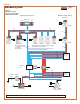
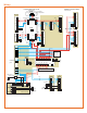
1 1-1 SYSTEM CONFIGURATIONS a e c d Max. 48 Max. 25 / Trunk (1) (2) (3) [9] GH-1KD b GH-VA + GH-DA + GH-NS, GH-10K [1] GH-VBC [6] GH-VA [5] [7] PS GH-DA GH-VA + GH-DA + GH-SW [10] GH-1KD [10] GH-1KD [10] GH-1KD [9] GH-1KD [10] [5] [8] GH-4Z Max. 6 [10] GH-1KD PS Max. 5 (3 per trunk) [10] GH-1KD PS GH-BC GH-4Z Max. 6 GH-1KD [10] 2 [5] [10] GH-1KD #6 ~ #2 [10] a Max. 48 Max.
1-1 Standard System Configuration Diagram (1) Audio signal line (2) Video signal line (3) Power supply line a. Entrance station (For details, see 2-1 and 2-2) [1] Video/audio + digital name scrolling type GH-VA + GH-DA + GH-NS, GH-10K [2] Video/audio + direct selection type GH-VA + GH-DA + GH-SW [3] Audio + digital name scrolling type GH-DA + GH-NS, GH-10K [4] Audio + direct selection type GH-DA + GH-SW b.
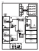
1-2 1 2 #1 a e f #2 #1 b c (d) #2 b c (d) #3 b c (d) #4 b c (d) a (1) (2) (3) e :A :V :P #1 #1 a f [1] GH-VBX #2 GH-VA + GH-DA + GH-NS, GH-10K #3 #4 [4] PS GH-VA GH-DA Max. 8 (3 per trunk) e GH-MK 1 2 A B D G 5 I J K M N PQ T WX PS Y Max. 2 PS [4] c (d) [2] GH-BCX [4] PS a GH-VA + GH-DA + GH-NS, GH-10K #2 [3] DP [4] PS #2 GH-VA GH-DA #4 GH-BC e GH-MK 1 2 A B D G 5 I J K M PQ T Y Max.
1-2 1-3 Expanded System Configuration Diagram 1. Common trunk line #1, 2 2. Sub trunk line #1 - 4 Sub trunk line #2 - #4 are the same as #1. Maximum 125 units per sub trunk line. (1) Audio signal line (2) Video signal line (3) Power supply line a. Entrance station (For details, see 2-1 and 2-2) b. Bus control unit c. Residential station (For details, see 2-4): Station-to-station wiring (For details, see 1-1) d.
2 2-1 [1] [2] [3] [4] [5] [6] [7] [8] [9] [10] [11] [12] [13] [14] [15] [16] [17] [18] [20] [19] [20] [21] [22] [23] [24] [25] Unit (Entrance Station) [1] Speech module panel GH-DP [2] Speech module GH-DA [3] Camera module panel GF-VP [4] Camera module GH-VA [5] 1-call button panel GF-1P [6] 2-call button panel GF-2P [7] 3-call button panel GF-3P [8] 4-call button panel GF-4P [9] Call switch module GH-SW [10] Digital name scroll module panel GF-NSP [11] Digital name scroll module G
2-3 2-2 1 [1] 2 [2] [3] AIPHONE AIPHONE 3 [4] [5] [6] [7] [8] [9] 4 AIPHONE AIPHONE Combination Example for Entrance Station 1. Audio only. Direct selection (8 stations). 2. Video/audio. Direct selection (8 stations). 3. Audio only. Digital name scrolling. 4. Video/audio. Digital name scrolling.
2-4 [2] [1] [3] [2] 1 2 A G H I 3 5 J K L P 8 W T U V E F 6 M S B C D 4 7 Q R N O 9 X Y Z [1] 2-5 0 [4] [5] [6] Security Guard Station [1] Security guard station GH-MK [2] Mounting screws (enclosed with GH-MK) [3] RS-232C cable (enclosed with GH-MK) Residential Station [1] Audio residential station GH-1AD [2] Color monitor residential station GH-1KD [3] Mounting screws (enclosed with GH-1AD and GH-1KD) [4] Black-and-white monitor residential station GH-1MD [5] Mounting scr
3 3-1 1 [1] [2] 200mm (7-7/8") [1] 25mm (1") [2] [3] Mounting the Entrance Station (1) [1] Back box [2] Joint pipe [3] Back box assembly dimensions [4] Special screwdriver (enclosed with GH-BC) 1. Mounting the back box • Make a hole for the cable. • Use the joint pipe to assemble the back box. • Make sure the back box is mounted level. • Mount the camera and GH-NS module at eye-level for the average height of an adult.
3-2 3-3 1 1 GH-DA GH-DA CN3 GH-NS CN1 CN2 GH-VA CN3 CN1 ON CN1 1 2 3 GH-DA 4 CN2 CN1 103 CN100 CN2 GH-AD 2 GH-10K 3 GF-C 2 ON 1 2 3 4 GH-VA GH-NS GH-DA GH-10K GH-AD GF-BP GF-3B GF-3B 103 GH-DA GH-DA ON 1 2 3 4 ON CN2 103 GF-3B GH-SW ON 1 GF-3B GF-3B GF-C 2 ON CN1 3 CN2 Mounting the Entrance Station (3) 1. Example of interconnection of modules. 2. Use GF-C to connect to the name scrolling module. 3.
3-4 1 Bus Control Unit and Power Supply Adapter [1] Din rail (W-DIN11) [2] Screw hole [3] POWER switch [4] Power On LED (green) [5] Lock release lever [6] Wall mounting screws (x2) 1. Mount GH-BC and GH-VBC to the Din rail. Click unit into place. ∗ To remove GH-BC and GH-VBC, pull the lock release lever down. ∗ If there is a problem with the system, check the power supply wiring. Turn off the GH-BC and GH-VBC power switch and then turn the switch back on after four seconds.
3-5 3-6 [3] GH-1AD GH-1KD [1] 1 [2] [2] [1] [3] 83.5mm (3-5/16") OR 60mm (2-3/8") [3] 2 SW1 A B Do not remove the wires (For end users) IN OUT 0.65 10 9 R1 R2 R1 R2 C CE K KE [4] SW1 A users) es (For end e the wir 10 9 not remov OUT 0.65 K KE B Do IN CE R2 C R1 R1 R2 Optional Handset [1] Chassis [2] Handset (GH-HS) [3] Screws (x2) • Connect the station unit joint connector. GH-HS can be installed only for the color monitor residential station (GH-1KD).
3-7 3-8 1 2 [2] [1] [1] 83.5mm (3-5/16") 1 G P H I S K L M R 3 E 5 J Q C D 7 B T U V N OR O W 9 X 0 F 6 8 Y Z A 4 2 60mm (2-3/8") [2] 3 [1] [3] 4 5 [4] 1 2 A B 3 C D E 4 G H 5 I J K M PQ 8 R T V Security Guard Station (Mounted on Wall) [1] 1-gang box or round back box [2] Mounting bracket [3] Wiring slot [4] Terminal block 1. Mount the mounting bracket on the 1-gang box. 2. Connect the wiring to the terminal block. 3.
4 4-1 WIRING a c (d) b e [9] PS-2410LC PS-2410LD AC PS-2410DIN AC PS AC a GH-NS #1 1P NP 1P NP A1 A2 A1 A2 A1 A2 A1 A2 A1 A2 b GH-VA #1 1P NP 1P NP 1P NP PS GH-VA #2 - #5 GH-NS #2 - #5 SW2 [1] STD EXP A1 A2 A1 A2 A1 A2 A1 A2 A1 A2 IN1 IN2 IN3 IN4 IN5 GH-VBC [10] GH-VBC OUT1 OUT2 OUT3 OUT4 OUT5 OUT6 + – + – [4] NP 1P 1P NP GH-DA #1 GH-10K #1 B1 B2 B1 B2 B1 B2 B1 B2 B1 B2 B1 B2 NP – 1P + NP PS 1P CN1 NP CN3 A1 A2 CN3 1P A1A2 NP + – 1P 9mm B1 B2 B1 B2 B
4-2 4-1 a b e Standard System (1) [1] Entrance Station [2] Door release timer (set to "M" at time of shipment) • Set the duration for the door release function when the door release button is pressed. [0.5] - [20]: 0.5 secs - 20 secs [20] - [M]: Activates while the button is pressed. [3] Setting switch (GH-DA) • SW2: 1: Setting switch for camera entrance station monitoring function (set to OFF at time of shipment) ON (Up): Monitored. OFF (Down): Skipped at time of entrance station monitoring.
4-3 GH-1MD a b e d d 1P NP B1, B2 B1 B2 R1 R2 C CE K KE Do not remove the wires! GH-4Z 1P NP R1, R2 GH-1AD A IN OUT R1R2 R1R2 C CE K KE B SW1 R1, R2 B1 B2 R1 R2 B1 B2 R1 R2 GH-4Z B1 B2 R1 R2 1P NP SW1 A B GH-4Z [2] GH-1KD IN OUT B1B2 B1B2 B1 B2 R1 R2 1P NP B1 B2 R1 R2 IN OUT R1R2R1R2 C CE K KE B1 B2 R1 R2 1P NP [2] [3] 1P NP K KE A 1P NP B SW1 SW1 A B1 B2 R1 R2 B1 B2 R1 R2 B [2] GH-1KD B1 B2 R1 R2 IN OUT B1B2 B1B2 GH-4Z IN OUT R1R2R1R2 C CE K KE 1P NP [3] B1 B2 R1
4-3 Standard System (2) Homerun Wiring [1] 4-way video junction unit GH-4Z • For the terminating GH-4Z (maximum of 6 units per trunk), set the setting switch to "A". [2] Residential station GH-1KD, GH-1AD, GH-1MD • For GH-1KD and GH-1AD, set the setting switch to "A". [3] Short lead • To use the emergency alarm switch (see 11-7 for details), disconnect the short lead and connect the switch. [4] External relay GH-RY For details, see 4-5.
4-4 f 1 2 a e 1P NP 1P NP 1P NP GH-VBX b b b b f a e [3] (d) (d) (d) (d) c c c c B1 B2 B1 B2 CN2 CN2 B1 B2 B1 B2 B1 B2 B1B2 B1B2 B1B2 SUB1 SUB2 1P NP 2 b GH-VBC GH-VBX A1 COMMON1 COMMON2 A1A2 A1A2 A1A2 A1A2 A1A2 A1A2 A1A2 A1A2 A1A2 A1A2 A1A2 A1A2 A1A2 A1A2 A1A2 A1A2 A2 A1 A2 A1 A2 A1 A2 A1 A2 A1 A2 IN1 IN2 IN3 IN4 IN5 A1 A2 A1 A2 A1 A2 A1 A2 A1 A2 A1 A2 A1 A2 A1 A2 GH-VBC 1 OUT1 OUT2 OUT3 OUT4 OUT5 OUT6 + – 1P NP 1P NP 1P NP [1] a [4] GH-VA #1 B1 B2 B1 B2 B1 B2
4-5 4-4 Expanded System 1. Common trunk line: maximum of 2 trunk lines 2. Sub trunk line: maximum of 4 trunk lines Maximum of 125 units (maximum of 48 units for standard system) • The wiring of the sub trunk line is the same as the standard system. For details, see 4-1 to 4-3.
5 6 6-1 NAMES (ENTRANCE STATION) 1 GH-VA NAMES (RESIDENTIAL STATION) GH-NS [1] [5] [6] [7] [9] [8] N O [10] 9 T Z C W I K M S [10] [9] E 6 8 U GH-10K 3 D P Q R J G H 7 [3] [4] B 5 [1] F 2 A 4 L 1 [2] V GH-DA GH-1AD X Y 0 [3] 2 [2] GH-DA [8] [6] [5] [7] [4] GH-1KD GH-SW [11] [12] [11] [10] [9] [1] Entrance Station 1.
6-2 7 NAMES (SECURITY GUARD STATION) GH-1MD [1] [2] 2 I S 8 T [7] N U 0 [12] E 6 K W [5] 3 5 M P 7 Q R B D H J G [7] [3] 4 C 1 A [4] [5] [6] [8] F [3] [4] O [10] [9] 9 Z [9] [1] L [8] V [2] GH-MK X Y [10] [11] [13] [14] [6] Residential station (GH-1MD) [1] Video monitor 4 inch black and white CRT [2] Microphone [3] Speaker [4] Light button / Security guard station call button [5] Door release / Monitor button [6] Talk button [7] Talk LED [8] Monitor brig
8 8-1 8-2 SETTING UP (ENTRANCE STATION) 1 GH-SW GH-VA 95cm 65cm 65cm GH-AD 50cm 2 GH-VA GH-VA Entering Names and Addresses • Remove the resident name/address plate or paper by pressing the left or right end. (Peel off the plastic film.) • Use a permanent pen to write the resident name and address on the transparent plate and mount the plate on the module. 3 GH-VA 50cm 113cm 24cm 113cm 24cm [1] [2] Adjusting the Camera Angle 1. View from the initial camera position 2.
8-3 [1] [1] Making Adjustments with the Mounting Gauge [1] Mounting gauge • To mount multiple rows of panels, apply the mounting gauge to the mounting bracket. While using the mounting gauge to make adjustments, tighten the screws. ∗ There is a mounting gauge for the built-in back box of GF-2B and GF-3B.
8-4 1 2 Setting up the System 1. Make sure that all units are installed and wired properly. Turn on the power switch to GH-BC. When the system includes GHNS, program the resident information (names and room numbers) in advance. (For details, see 8-5) 2. Loosen the base screw and open and remove the front panel. 3. Set the system to program mode. • Lift up the rubber cap. • Press the program switch once. Use any long thin tool, such as a fine screwdriver.
8-5 Programming (GH-NS) a. Programming with a PC • You can use a PC to enter data and write in or change resident names. • Use the connection cable that comes with GH-NS to connect your PC to GH-NS. • In your PC, install the setup tool program from the CD that comes with the GH-BC. ∗ For information on how to use the setup tool, see the text (.txt) file that is installed in the same folder as the setup tool (.exe). b.
8-6 5 YOUR OPERATION DISPLAY YOUR OPERATION SET TIMER SELECT LANGUAGE DECIDE & NEXT DECIDE & NEXT MENU ENGLISH FRANCAIS DEUTSCH BACKWARD FORWARD ESPANOL Scroll NEDERLANDS OPERATION TIMER 15 3 0 D DECIDE & NEXT 2-digit (15-99) W PROGRAM TIMER 60 SELECT LANGUAGE ENGLISH E F DISPLAY 9 Z 1 X Y 0 2-digit (30-99) Menu 2 DECIDE & BACK CALL DURATION 45 6 0 O M N 2-digit (30-99) 2 DISPLAY YOUR OPERATION CHANGE ID CODE Menu 6 Move cursor DECIDE & BACK DECIDE & NEXT F WELCOME
8-6 Program Mode (GH-NS) 1. Menu 1: Select language Choose language to be displayed on GH-NS. 2. Menu 2: Change ID code Enter new ID code starting with "∗", then 4-digit number. (Example: ∗1234) 3. Menu 3: Set access code Enter new 4-digit Access Code. (Example: 1234) • (0000) cannot be registered as an access code. • Recommend not to use a simple access code such as (1111). 4. Menu 4: Write in resident information Register room #s and resident names. Enter room #s using 1 to 6-digit characters.
9 9-1 SETTING UP (SECURITY GUARD STATION) a 2 GH-MK 1 A 2 B G H C 3 D 4 I E J 5 K L R N S 8 T U F 6 M P 7 Q V O W 9 X Z Y 0 PC b Enter Program Mode DISPLAY YOUR OPERATION AIPHONE 1 1 1 1 INITIAL ID CODE RE-ENTER ID CODE 1 1 1 3 1 INITIAL ID CODE ID CODE = + 4 digit Select Menu & Quit DISPLAY YOUR OPERATION 4 SELECT LANGUAGE 101 SMITH BACKWARD FORWARD MENU Scroll Go to Menu 1-7 1 2 G 4 H I K 3 L S R T 8 U E F 6 M P 7 Q C 5 J DE
9-1 Programming (GH-MK) • Make sure that all units are installed and wired properly. Turn on the power switch to GH-BC. Program the resident information (names and room numbers) in advance. a. Programming with a PC • You can use a PC to enter data and write in or change resident names. • Use the connection cable that comes with GH-MK to connect your PC to GH-MK. • In your PC, install the setup tool program from the CD that comes with GH-BC. ∗ For information on how to use the setup tool, see the text (.
9-2 1 DISPLAY 5 YOUR OPERATION SELECT LANGUAGE DISPLAY YOUR OPERATION PROGRAMMING<< DECIDE & NEXT MENU DECIDE & NEXT ENGLISH FRANCAIS BACKWARD FORWARD DEUTSCH ESPANOL Scroll NEDERLANDS SELECT LANGUAGE ENGLISH PROGRAMMING<< CONNECTING... Menu 2 DECIDE & BACK PROGRAMMING<< CONNECTING...
9-2 Program Mode (GH-MK) 1. Menu 1: Select language Choose language to be displayed on GH-MK. 2. Menu 2: Change ID code Enter new ID code starting with "∗", then 4-digit number. (Example: ∗1234) 3. Menu 3: Write in resident information Register room #s and resident names. Enter room #s using 1 to 6-digit characters. Enter resident name (up to 16 characters). 4.
Calling a Residential Station 1. Direct Selection GH-SW • Press the call button for the residence that you want to call. You will hear a low-volume call tone from the entrance station. 2. Digital name scrolling GH-NS • Display the resident name you want to call and press the call button. You will hear a low-volume call tone from the entrance station. a. Making a call by name scrolling b. Making a call by entering the room number c.
10-3 WELCOME YOUR OPERATION Enter Access Code 4567 J P S M 8 W T U V E F 5 I H K 6 N 7 Q R 6 N O ACCESS CODE 9 X Y Z G K L M 3 5 J B C D 7 Q R G 2 A H I P 4 1 4 S DISPLAY O 1 L 10-2 0 DOOR OPEN When there is no code, DENIED 2 Calling the Security Guard Station Press the call button once. You will hear a low-volume call tone from the entrance station. Door Release 1. Enter the access code. (8-6, Menu 3) 2.
11 OPERATIONS (RESIDENTIAL STATION) 11-1 1 11-2 1 2 2 Call from the Doorbell Button (Individual Entrance Door) 1. The doorbell button is pushed. A call tone sounds as long as the button is held down. 2. A different call tone sounds (there is no communication available). 3 Responding to a Call 1. When the call is from an entrance station or security guard station, the call tone will ring at the residential station for approximately 10 seconds. An image will be displayed on monitor residential station.
11-3 1 11-4 2 1 Door Release 1. Press the door release button while in communication. 2. The door release function will activate on the entrance station that is in communication. ∗ Depending on the electric door release system that you use, the door release may be active only while the door release button is pressed. 2 Turning on the Entrance Light 1. Press the light button once while in communication. 2. The outside light of the entrance will turn on for the preset duration of time.
11-5 11-6 1 2 A G 3 5 J K L P 8 W T U V E F DOCTOR 6 M S B C D H I N O 9 X Y Z 1 4 7 Q R 2 0 Calling the Security Guard Station Press the light/security guard station call button on the residential station. You will hear a low-volume call tone. When the system is being used for communication, an in-use tone will be heard at the residential station. (The call is only invalid when a communication link has not been established.) 3 4 Automatic Entry (Doctor Call) Option 1.
11-8 11-7 1 2 X Beep, Beep, Beep 3 4 Entrance Monitoring With a monitor station, you can monitor entrance stations if you press the door release button in standby mode. You can switch between the entrance stations by pressing the door release button. NOTES: 1. Entrance monitoring is possible for only one residential station at a time. 2. If you press the talk button while monitoring, you can communicate with that entrance station. 3. If a call is received while monitoring, monitoring is terminated. 4.
12-2 12 OPERATIONS (SECURITY GUARD STATION) 12-1 1 1 A 2 G J P 8 S E F 6 M P S E F N O 9 X Y N O W T 9 X Y Z J K L W 5 8 U V T G H I U V 0 3 D 4 7 Q R B C 6 K L M A 2 D 1 3 B C 5 H I Z 1 4 7 Q R 0 2 3 3 1 1 2 Z S M P S S K C 3 L U V N F O 9 X 0 E 6 8 Y F O T W Z Y Responding to a Call from a Residential Station 1.
12-3 12-4 1 2 1 1 B C 3 K L S Z N W 6 M a N DISPLAY J 3 L E F 101 1 2 H I R B C K L T U E F 6 8 V E F 6 N O 9 Y N O Press button intermittently or hold down for 2 sec. to show in succession.
12-5 12-6 1 4 G X H 1 1 2 4 3 L E H F 5 I K N O 8 R T V O Y 1 G 4 H I 2 K L 3 P 8 W T U V E F 6 M S B C 5 J 7 Q R D CALL A p, Beeep, Be ep Be F 6 9Z 0 Y Z W 9 X WX T U V L N 7S 6 PQ S C M P U 0 M K 8 3 E C D B 5 J R J I 7 G G H D 4 Q B A A 2 N O 9 X Y Z 1 EMERGENCY I 0 1 0 2 Calling Another Security Guard Station Lift the handset and press the "∗" button and "1" button.
12-7 12-8 1 2 1 2 A B 3 C D E 4 G H 5 I J K M PQ 8 R T V O 9Z WX U F 6 L N 7S Y 0 Call from the Doorbell Button 1. The doorbell button is pushed. A call tone sounds as long as the button is held down. 2. A different call tone sounds (there is no communication available).
13 14 TECHNICAL PRECAUTIONS Technical precautions • Operating temperature: Entrance Station: -10 - 60 °C Residential Station: 0 - 40 °C Security Guard Station: 0 - 40 °C Control Unit: 0 - 40 °C • Mounting location: Do not install the entrance station in a place where there would be a bright light behind a visitor (or where there would be a bright background) or in a place where the camera lens would be directly exposed to sunlight or a bright light.
This equipment has been tested and found to comply with the limits for a Class B digital device, pursuant to Part 15 of the FCC Rules. These limits are designed to provide reasonable protection against harmful interference in a residential installation. This equipment generates, uses, and can radiate radio frequency energy, and if not installed and used in accordance with the instructions, may cause harmful interference to radio communications.