0311 A OI 6(59,&( 0$18$/ GT SYSTEM Apartment Intercom System Installation manual
PRECAUTIONS General Prohibitions Prohibition to Dismantle the Unit Prohibition on Subjecting the Unit to Water General Precautions WARNING (Negligence could result in death or serious injury.) 1. The units must be installed and wired by a qualified technician. Having installation performed by an unqualified technician could result in electric shock. 2. Do not dismantle or alter the unit. Fire or electric shock could result. 3. Do not connect non-specified power sources to the +, - terminals.
-3-
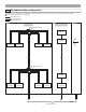
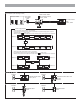
1 SYSTEM CONFIGURATIONS 1-1 Standard system configuration This system is constructed with a 2-line communication system and a 2-line video system and requires minimal work for installation. The system is constructed with video trunk lines consisting of a maximum of 6 trunks from the video bus control system and communication trunk lines that use a distribution point from a bus control unit. In addition, systems with audio only can be configured.
1-2 Expanded system configuration diagram The wiring of the sub trunk line is the same as the standard system.
1-3 Residential station configuration For wiring from the control units to each residence, station-to-station wiring or star wiring using a 4-way video junction unit is possible. Mixing on the same trunk line is not possible.
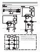
Each residence (with recording function) Master monitor station (with recording function) GT-2C-L, GT-2C Door station or doorbell GT-D Video door station Sub master monitor station GT-2H-L, GT-2H AIPHONE JF-DVF PS24 Power supply-related [When sub master monitor stations are connected] If even just one sub master monitor station is connected, it is possible to supply power to up to 2 power supply.
1-4 Wiring distance Standard system Expanded system Each residence Each residence (with recording function) Each residence PS24 * Each residence DP PS24 Each residence PS24 * DP DP PS24 PS24 1 2 3F A Entrance station B C D E 4I G 5L H J 6 M K N O 7R S PQ 8 T 9Z WX U V Y 0 2 A G 5 J H I K L M P 7 S 8 T U V W Q R 3 D 4 B C E F 6 N O 9 X Y Z 1 0 Entrance station 1 2 A 3F B C D E 4I G 5L H J 6 M K N O 7R S PQ 8 T 9Z WX U V Y 0 2 A
Wire diameter Wiring distance 0.65 mm (22 AWG) 0.8 mm (20 AWG) 1.
2 2-1 COMPONENTS Entrance Station (Unit type) Panel Module Speech module panel (guidance-enabled type) GT-DP-L Speech module (guidance-enabled type) GT-DA-L (connector included) Speech module panel GT-DP Speech module GT-DA (connector included) Camera module panel GT-VP Camera module GT-VA (connector included) 1-call button panel GF-1P 2-call button panel GF-2P Switch module GT-SW (connector, name card included) 3-call button panel GF-3P 4-call button panel GF-4P Name scrolling module (VIGIK-li
Mounting parts 4-module front frame GT-4F Mounting bracket (included with GT-4F) Screws 3-module front frame GF-3F Mounting bracket (included with GF-3F) 2-module front frame GF-2F 4-module back box GT-4B 3-module back box GF-3B 2-module back box GF-2B Rain hood GT-nH Mounting bracket (included with GF-2F) Joint pipe Mounting gauge Hooded surfacemount box GT-nHB Surface-mount box GF-nBA 80 cm (32") connection cable GF-C * A number appears in place of n.
2-2 Entrance Station (Integrated type) USB cable A-B type (1 m) Flush mount entrance station (name scrolling, guidance-enabled, VIGIK-linked type) GT-DMV Flush mount entrance station (name scrolling, guidance-enabled) GT-DM Screws 2-3 Bus control unit etc.
Residential station GT-1A Wood mounting screws Screws Residential station GT-1D Optional handset GT-HS Residential monitor station with handset GT-1M-L 2-5 Option connector Door station For door stations other than the GT-D, see the instruction manual for that door station.
3 3-1 MOUNTING Mounting locations • For video entrance stations and video door stations, the picture quality of residential station monitoring is affected by the nature of the external light from above and the surrounding area of the built-in cameras, so do not install these stations in the types of locations shown below.
3-3 Mounting positions and image view area When using the camera module, if the rain hood is attached a portion of it will show up in the camera display. Wide picture Mounting position 1350 mm (4' 4") Up/Down Approx. 1800 mm (5' 11") Approx. 2000 mm (6' 7") Mounting position 1550 mm (5' 1") Camera center Approx. 1050 mm (3'5") Approx. 1050 mm (3'5") Camera center Approx. 950 mm (3' 2") 1350 mm (4'4") Approx. 750 mm (2' 5") 1550 mm (5'1") 500 mm (20") 500 mm (20") Left/Right Approx.
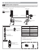
3-4 Entrance Station (Unit type) 1 2 Joint pipe Back box Make a hole for the cable. Use the joint pipe to assemble the back box. • Make sure the back box is mounted level.
6 Remove the terminal cover. 7 From the speech module to the next module, insert the attached connector into the socket. Make sure to run the cable under the terminal cover for protection. 8 Connect the connectors between the modules with cables. Mount modules on the back boxes. Example of interconnection of modules Use the GF-C to connect to the name scrolling module. To position the speech module in the center row, run the GF-C through the joint pipe in advance.
3-5 Entrance Station (Integrated type) 1 Open the cover and connect the wiring to the terminal block. Insert the wire into the direct terminal. If it is difficult to insert the wire, insert it while pressing the release button. 2 Close the cover until it clicks into place. 3 Mount the unit in the flush mount back box. 4 Tighten the locking screws using the special screwdriver.
3-6 Bus control unit, 4-way video junction unit and power supply DIN rail mounting The length of the connecting cable between the GT-BCX and GT-VBX is 40 cm. Therefore, mount them adjacently to each other. 1 2 Mount the unit on the DIN rail. Click the unit into place. When removing the unit, pull the lock release lever down. * When the system does not operate properly, check the wiring. Turn off the GT-BC and GT-VBC power switch and then turn the switch back on after four seconds.
3-7 Residential station Mounting screws ×4 3-gang box 83.5 mm (3-5/16") Mounting bracket 1. Press the release button (to insert or remove the wire). 2. Insert the cable into the terminal. • To remove the terminal block, slide the terminal block and pull it out. • Strip away the jacket of the cable and insert all wires into the slots in an orderly fashion. Failure to do so could result in pinching that may damage the wiring.
Mounting screws Mounting bracket 1-gang box 1 Mount the mounting bracket on the 1-gang box or round back box. 2 Connect the wiring to the terminal block. 83.5 mm (3-5/16") OR 60 mm (2-3/8") Mounting screws Round back box • To remove the terminal block, slide the terminal block and pull it out. • Strip away the jacket of the cable and insert all wires into the slots in an orderly fashion. Failure to do so could result in pinching that may damage the wiring.
1 Chassis Mount the station unit to the chassis or mounting bracket. 1-gang box Screws 83.5 mm (3-5/16") 2 Connect the wiring to the terminal block. GT-1M-L: • To remove the terminal block, slide the terminal block and pull it out. • Strip away the jacket of the cable and insert all wires into the slots in an orderly fashion. Failure to do so could result in pinching that may damage the wiring.
3-9 Security guard station Peel off the protection film on the display. Desk-top mounting using the GFW-S stand Screws included with GFW-S (×4) Mounting bracket Mounting bracket Protective cover 1 Separate the mounting bracket and the protective cover from the back of the unit. 2 Mount the mounting bracket to the GFW-S as shown in the drawing. 3 Strip away the jacket of the cable and insert all wires into the slots in an orderly fashion while connecting them to the terminal block.
4 WIRING Standard system for common area Put each piece of wiring in a separate sheath as shown in the diagram below. #1 A1 A2 Entrance station #1 to #3 Ex.
Bus control unit PS24 + 230 V AC N Video bus control unit GT-VBC - L IN 230V~ 50/60Hz NL 2A - + 100V - 240V 50/60 Hz + 24V DC 2A A1 A2 A1 A2 A1 A2 IN5 1P NP A2 IN4 1P NP A1 IN3 1P NP A2 IN2 1P NP A1 IN1 1P NP OUT6 OUT5 OUT4 OUT3 OUT2 OUT1 24 V DC2A STD EXP SW2 B1 B2 B1 B2 B1 B2 B1 B2 B1 1P NP Residence trunk (1) 1P NP Residence trunk (2) 1P NP Residence trunk (3) 1P NP Residence trunk (4) 1P NP Residence trunk (5) B2 B1 1P NP Residence trunk (6) B2 + PS24 - AC
4-2 Standard system for residence (station-to-station wiring) Residential station GT-2C-L GT-2C JK-DA JK-DV JK-DVF Audio only GT-1C-L GT-1C Terminal setting: For the terminating residential station, turn SW1 to the [A] side. Door station Terminal setting: For the terminating residential station, turn SW1 to the [A] side.
4-3 Standard system for residence (homerun wiring) Residential station Residential station SW1 A SW1 A B IN IN B1 B2 R1 R2 B1 B2 R1 R2 GT-4Z Terminal setting: For the terminating 4-way video junction unit, turn SW1 to the "A" side. In this case, 1 residential station can be connected to [LINE OUT].
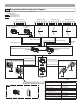
4-4 Expanded system Common trunk line system (1) A2 GT-DA-L/GT-DA SW2: 2~4 #1 #2 ON ON 1 2 3 4 #3 ON #4 DP A1 A2 R1 R1 R2 R2 R2 + + + - - - 1P NP A1 A2 1P NP PS24 A1 A2 1P NP A1 AC A1 A2 A2 1P NP #6 A1 A2 1P NP A1 DP R1 R1 R2 R2 R2 + + + - - - B2 1 2 3 4 1P NP A1 A1 R1 R1 A2 CN2 R2 R2 + + - - 1P NP PS24 1P NP CN1 SUB 1A R2 DP R2 R1 R1 + 1P NP 5 + - 3 2 1 R2 1P NP R2 - 4 1P NP 10 9 8 7 6 R1 R1 R2 R2 PS24 R1 AC Bus cont
Put each piece of wiring in a separate sheath as shown in the diagram below.
• Expanded video bus control unit GT-VBX Connector cable length: 40 cm • Expanded bus control unit GT-BCX There are 4 groups each of R1 and R2 terminals on each trunk line terminal including COMMON1, COMMON2, SUB1A, SUB1B, SUB2A, and SUB2B. Terminals with the same name are connected together in the same trunk line terminal, so these trunk line terminals can be used as distribution points. For connecting the lift control adaptor GTW-LC, refer to the GTW-LC Installation & Operation Manual.
Emergency alarm The emergency alarm switch can be connected. N/C contact (locked type) DC 12 V/0.1 A or higher Video out Video can be output to DVRs etc. (NTSC, 1 Vp-p/75 ) Wiring distance: 3 m NOTES: When a video signal is output, residential stations may produce a sound depending on the installation environment. (The screen playing recorded pictures is not output.) Call notification Using the external signaling relay GT-RY allows for the external buzzer to be linked during calling.
5 SETTINGS (COMMON AREA) 5-1 Setting list Perform the following settings at an entrance station or security guard station. Depending on the setting item, some items are set by switching DIP switches and some are set using the program mode menu. After any DIP switches are switched or any changes are made in the program mode, turn the power supply off and on again. In some cases, the settings may not be changed. • The program menu varies according to the unit.
5-2 Setting method Program Mode Settings can be performed with the GT-NS-V/GT-NS, GT-DMV/GT-DM, and the GT-MK. Programming cannot be performed from a security guard station if there is a record of an emergency alarm. 1 Check on the display that the unit is in the standby mode. • When performing the initial settings, "WELCOME" will display at the entrance station and "AIPHONE" will display on the security guard station GT-MK.
5-3 Entrance station and security guard station ID setting IDs for entrance stations and security guard stations are set using the DIP switches of units. The setting shown with "#1" is the setting at the time of shipment. When installing multiple entrance stations and security guard stations, make sure to set IDs.
5-5 Writing resident information If the entrance station is a 10 key type or a GT-MK, program the resident information (names and room numbers) before performing the system settings. Up to 500 resident information entries can be registered. Programming with a PC • You can use a PC to enter data and write in or change resident names. • In your PC, install the setup tool program from the CD that comes with the GT-BC. A caution screen may display, but continue with installation.
5-6 Manual setting of residence IDs Residential station IDs are automatically assigned during link setting. However, with the GT-2C-L/GT-2C and GT-1C-L/GT-1C units only, they can be set manually using the switches on the unit. All are set to OFF in the initial settings. When replacing a residential station due to malfunction, resetting the link is unnecessary as the link can be maintained by adjusting the switches.
Performing settings from an entrance station 1 Check that all units are mounted and wired correctly, and then turn on the power switch of the GT-BC. 2 With the GT-DA/GT-DA-L, loosen the base screw of the frame and open and remove the front panel. ON ON GT-BC OFF GT-DMV/GT-DM Remove the rubber cap and use a fine screwdriver to push the program switch. With the GT-DMV/GT-DM, enter the program mode and select "PROGRAMMING" from the menu. Wait until "CONNECTING..." is displayed.
GT-DMV/GT-DM 6 Press the OFF button to finish programming. With the handset type module, return the handset. Repeat steps 3 to 6 to program all residential stations. 7 Press the program switch of the GT-DA-L/GT-DA to finish programming. The in use LED will go out. For the GT-DMV/GT-DM, press the button. GT-DA-L/GT-DA PROGRAMMING CONNECTING...
Performing settings from a security guard station ON ON 1 Check that all units are mounted and wired correctly, and then turn on the power switch of the GT-BC. 2 Enter the program mode at the GT-MK and select "PROGRAMMING" from the menu. Wait until "CONNECTING..." is displayed. 3 Lift the handset of the GT-MK. 4 Press and hold down the door release button while holding down the security guard station call/light button of the residential station.
5-8 Transferring link information Transfer link setting information set at an entrance station or security guard station to other entrance stations and security guard stations. Enter the program mode and select "TRANSFER DATA".
5-9 Link check Performing settings from an entrance station (Unit type) Press the program switch of the GT-DA-L/GT-DA for at least 5 seconds. The in use LED will light up after blinking. GT-SW: Press the relevant call button. GT-NS-V/GT-NS: Select the room and press the GT-DA-L/GT-DA button. An electronic sound will be emitted once if the link is normal. If the link is abnormal, an error sound will be emitted.
5-10 Setting the input timeout timer Enter the program mode with the GT-NS-V/GT-NS, GT-DMV/GT-DM or GT-MK and select "SET TIMER". • Operation timer: If the operation panel is not operated for a certain period of time, the system returns to standby mode. The initial setting is 15 seconds. • Program timer: If an operation is not performed for a certain period of time in the program mode, the program mode will automatically be cancelled. The initial setting is 60 seconds.
5-11 Display language selection Start the program mode with the GT-NS-V/GT-NS, GT-DMV/GT-DM or GT-MK and select "SELECT LANGUAGE". The initial setting is English. Select English, French, German, Spanish, Dutch, or Italian.
5-13 Setting messages and the standby screen GT-NS-V/GT-NS: Use 3 of SW1 to change the greeting message to an operation message. The initial setting is for a greeting message. GT-NS-V/GT-NS SW1 ON 1 2 3 4 Operation message Greeting message 3 GT-DMV/GT-DM: Start the program mode and select "STANDBY SCREEN". GT-DMV/GT-DM MENU STANDBY SCREEN BRIGHTNESS SORT SETTING :ENTER STANDBY SCREEN Select from the following in the standby screen display.
5-14 Room number display setting Set the entrance station display to show room numbers or to display only resident names. The initial setting is for the room number to also display. GT-NS-V/GT-NS: Switch this setting with 2 of SW1. GT-NS-V/GT-NS SW1 ON 1 2 3 4 Display only resident name Display room number also 2 GT-DMV/GT-DM: Enter the program mode and select "DISPLAY ROOM NO.". Select ON (room number also displays) or OFF (only resident name displays). MENU CALL-IN DISPLAY LIGHT OR CCTV DISPLAY ROOM NO.
5-16 Setting the sort order for searching Select either name order or room number order for searching at entrance stations and security guard stations. The initial setting is name order. GT-NS-V/GT-NS, GT-DMV/GT-DM, GT-MK: Enter the program mode and select "SORT SETTING". SORT SETTING MENU STANDBY SCREEN BRIGHTNESS SORT SETTING :ENTER SORT SETTING SORT BY NAME Current search order SORT SETTING SORT BY NAME SORT BY ROOM NO.
5-17 Access code setting Up to 500 access codes can be set for door release at an entrance station. The number of digits for access codes can be set anywhere in the range from 4 to 6. The initial setting is 4 digits. * Setting the access code number of digits GT-NS-V/GT-NS, GT-DMV/GT-DM: Enter the program mode and select "ACCESS CODE". ACCESS CODE MENU ACCESS CODE RESIDENT INFO. SET TIMER :ENTER NO.
5-18 Entrance monitor setting Monitoring with the entrance station camera from a residential station can be set to be possible or not possible. The initial setting makes this not possible. GT-DA-L/GT-DA: Switch this setting with 1 of SW2. GT-DA-L/GT-DA SW2 ON 1 2 3 4 Monitoring possible Monitoring not possible 1 GT-DMV/GT-DM: Enter the program mode and select "MONITOR ENTRANCE".
5-20 Surveillance camera switching setting Select "LIGHT CONTROL" or "CCTV SWITCH" for the operation performed when the light button on a residential station is pressed. The initial setting is OFF ("LIGHT CONTROL"). GT-VA: Switch this setting with 2 of SW1. SW1 ON GT-VA 1 2 3 4 Surveillance camera switching Light control 2 GT-DMV/GT-DM: Enter the program mode and select "LIGHT OR CCTV". Select using the and buttons. MENU CALL-IN DISPLAY LIGHT OR CCTV DISPLAY ROOM NO.
5-22 LCD operation mode setting The LCD screen automatic ON function can only be set with the GT-DMV/GT-DM. The initial setting is sensor mode. • Sensor mode: The LCD will automatically turn ON due to the sensor when a person approaches. The detection distance changes depending on the direction that the person approaching is facing. • Energy saving mode: Detection is not performed by the sensor. When a button is operated, the LCD turns ON.
5-25 Entrance zoom picture pre-set The picture can be set to display at the position set for zoom picture display when a residential station is called from an entrance station. The initial setting is for display at the center. Perform this setting in the pre-set mode. In the case of direct select type entrance stations and residential stations without a ZOOM/WIDE function, this pre-set is not possible.
Quit the pre-set mode 1 2 Press the Quit the pre-set mode button to register the pre-set position. Press the program switch of the GT-DA-L/GT-DA to finish programming. 1 2 Press the button to register the pre-set position. Press the button to return to the menu. GT-DMV/GT-DM CAMERA PRESET CONNECTING... 5 CAMERA PRESET: 5 CONNECTING... ZOOM BY NO. 1-9 :ENTER GT-DA-L/GT-DA CONNECTING... PROGRAMMING CONNECTING...
5-27 Entrance night illumination setting At night, the illuminator LED automatically lights up during an entrance station call. It can be set to always be off if night illumination is unnecessary or it is too bright. The initial setting is for the LED to automatically light up. GT-VA, GT-DMV/GT-DM: Switch this setting with 1 of SW1.
6 Setting (GT-2C-L/GT-2C) 1. See the operation manual included with the GT-2C-L/GT-2C for the name and operating method for each part. 2. Actual screens may vary depending on the system. 3. When settings are changed, turn the unit power supply off and on again. In some cases, the settings may not be changed. 6-1 How to use the MENU 1 In the standby mode, press the [ ADJUST] button and [ 2 ZOOM/WIDE] button until the warning screen displays.
6-3 Emergency input settings Set emergency input to be enabled or disabled. 1 After performing steps 1 in section 6-1, select "ALARM INPUT" in the "INSTALLATION" screen and press the [ MENU] button. 2 Select "DISABLE", "N/O", or "N/C" in the "ALARM INPUT" screen. Press the [ MENU] button to complete the settings and return to the previous screen. ALARM INPUT DISABLE N/O N/C 6-4 External input setting Set external input (3 circuits) to security sensor or utility sensor.
Utility sensor setting (detection method) 4 When "UTILITY" is selected, select "N/O" or "N/C" in the "UTILITY-SENSOR DETECTION METHOD" screen and press the [ MENU] button. Security sensor (alarm transfer) 5 When [SECURITY] is selected, in the [EXTERNAL INPUT SETTING] screen, select [ALARM TRANSFER] and press the [ MENU] button.
6-5 Doctor call setting Set Doctor call to be enabled or disabled. 1 After performing steps 1 in section 6-1, select "DOCTOR CALL" in the "INSTALLATION" screen and press the [ MENU] button. 2 Select from "ENABLE/DISABLE" in the "DOCTOR CALL" screen. Press the [ MENU] button to complete the settings. DOCTOR CALL ENABLE DISABLE 6-6 Press-to-talk setting Set press-to-talk during communication to be enabled or disabled.
6-7 Initializing All settings can be restored to their condition at the time of purchase. 1. Recorded pictures are erased and settings are reset. 2. Pre-set functions are not reset.
- 59 -
Aiphone warrants that its products have no material or workmanship defects under normal use conditions for two years after delivery to the end user. Aiphone will perform repair or replacement free of charge if the product is defective and the warranty applies to the defect. Aiphone reserves unto itself the sole right to make the final decision whether there is a defect in materials and/or workmanship and whether or not the product is under warranty.