
Manual

5
NOTE: make sure that you have space between the bottom front part of
the sight and the top of the base/weapon.
d) Finally, make sure that all screws are firmly tightened around the sight.
e) Complete the zeroing (2.2.1).
2.2. OPERATING PROCEDURES
2.2.1. Zeroing
Aimpoint’s sights are delivered in a centered position. Normally this
means that only small adjustments are necessary, providing that the
base(s) are properly aligned.
CAUTION: Do not continue to adjust windage and elevation mecha-
nisms if you encounter resistance.
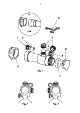
The elevation adjustment screw is located on top of the sight, while the
windage screw is located on the right or left side, depending on how the
sight has been mounted on the weapon. (Aimpoint sights can be installed
to support either right hand (fig 2) or left hand (fig 3) shooters.)
a) Open front and rear lens covers.
b) Turn the rotary switch clockwise until the red dot has a sufficient
intensity to contrast against the target.
c) Remove the windage and elevation adjustment caps.
NOTE: Each click of the adjustment screw corresponds to a 10 mm
movement of the point of impact at 80 meters, (3 mm at 25 meters, 13
mm at 100 meters and 25 mm at 200 meters or
1
/4” at 50 yds,
1
/2” at 100
yds and 1” at 200 yds).
d) Insert adjustment tool (coin, screwdriver, knife) or cartridge casing
in adjustment screw slot and turn as follows:
• To move the point of impact to the right, turn windage adjustment
screw counterclockwise (clockwise if screw located on left side).
• To move the point of impact to the left, turn windage adjustment
screw clockwise (counterclockwise if screw located on left side).