User´s Manual for Aimpoint CompM2 and Aimpoint CompML2 Aimpoint AB Jägershillgatan 15 SE-213 75 Malmö, Sweden Phone +46 (0)40 671 50 20 Fax +46 (0)40 21 92 38 e-mail info@aimpoint.se www.aimpoint.com Aimpoint Inc. 7702 Leesburg Pike Falls Church, Virginia 22043, USA Phone +1 (703) 749 2320 Fax +1 (703) 749 2323 e-mail info@aimpoint.com www.aimpoint.
1 CHAPTER I 1.1. Presentation Aimpoint’s Reflex Sights are rugged precision electronic optical red dot sights developed for civilian, military and law enforcement applications. Aimpoint sights are designed for the ”two eyes open” method of sighting, which greatly enhances situational awareness and target acquisition speed. Thanks to the parallax-free design, the dot follows the movement of the user’s eye while remaining fixed on the target, eliminating any need for centering.
2 Length (incl. lens covers): CompM2 / ML2: 130 mm (5.1”) CompM2-2X / ML2-2X: 165 mm (6.5”) Width / height: CompM2 / ML2: 55 mm (2.2”) CompM2-2X / ML2-2X: 60 mm (2.4”) Weight (incl. lens covers): CompM2 / ML2: 200 gram (7.1 oz) CompM2-2X / ML2-2X: 290 gram (10.2 oz) Adjustment: Range ±2,5 m at 100 meters, in windage and elevation 1 click = 10 mm at 80 meters = 13 mm at 100 meters = 1/2” at 100 yards.
3
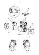
4 CHAPTER II OPERATION UNDER NORMAL CONDITIONS 2.1. ASSEMBLY AND PREPARATION FOR USE WARNING: Insure the weapon is unloaded and the safety selector is in the ”safe” position before attempting to install, remove or perform maintenance on the sight. 2.1.1. Installing Battery a) Remove battery cap by turning it counterclockwise. b) Insert battery with positive (+) end toward cap.
5 NOTE: make sure that you have space between the bottom front part of the sight and the top of the base/weapon. d) Finally, make sure that all screws are firmly tightened around the sight. e) Complete the zeroing (2.2.1). 2.2. OPERATING PROCEDURES 2.2.1. Zeroing Aimpoint’s sights are delivered in a centered position. Normally this means that only small adjustments are necessary, providing that the base(s) are properly aligned.
6 • To move the point of impact up, turn elevation adjustment screw counterclockwise. • To move the point of impact down, turn elevation adjustment screw clockwise. e) Confirm zeroing by firing at least three shots at a zeroing target. Check impact points on zeroing target to confirm accuracy and repeat above procedure if required. f) After initial firing, ensure that the mount and sight are secure. g) Turn rotary switch to OFF position (counterclockwise). h) Close front and rear lens covers.
7 CHAPTER IV TROUBLE SHOOTING PROCEDURES 4.1 RED DOT DOES NOT APPEAR Discharged battery Battery installed incorrectly Replace battery Remove and reinstall battery with (+) toward cap Battery is not making good contact Clean contact surfaces and reinstall battery. Defective rotary switch Notify dealer/armourer 4.