Acro C-1™ User manual
1 PRESENTATION Aimpoint® red dot sights are designed for the ”two eyes open” method which greatly enhances situational awareness and target acquisition. Thanks to the optical design the red dot follows the movement of the user’s eye while remaining fixed on target, eliminating any need for centering. 1.1 Technical specification Optical system Magnification 1X Eye relief Unlimited Clear aperture 16 mm (0.63 in) 16 mm (0.
Dot intensity settings 10 settings manually adjusted with push-buttons. Setting 1-2 for use with NVD and setting 3-10 for use in daylight. Signature No forward optical signature from the dot beyond 10 meters Power source Battery type CR1225 (3.0 V) Lithium Battery life3 More than 1.5 years of use on setting 6, more than 8 years on NVD-setting (1-2). Size (L × W × H) Sight 47 mm × 30 mm × 30 mm (1.9 in × 1.2 in × 1.2 in) Weight Sight (incl. battery) 60 g (2.
Materials Sight housing High strength aluminum, black to dark gray,non-glare finish Push-buttons Silicone rubber, black, non glare finish Environmental specification Temperature range (operation) -30 °C to +60 °C (-22 °F to +140 °F) Water resistance 5 m (15 ft) 1 MOA: Minute Of Angle, 1 MOA ≈ 30 mm at 100 m or ≈ 1” at 100 yds 2 NVD: Night Vision Device 3 Battery life: Values valid at room temperature for a quality battery
1.2 Overview 1 8 7 2 3 6 4 5 Fig.
2 OPERATION WARNING: Ensure the weapon is not loaded and the safety selector is in the ”safe” position before attempting to install, remove or perform maintenance. 2.1 Install battery a Unscrew and remove the battery cap (3) using a flat head screwdriver or similar. b Insert battery (2) with the positive end (+) toward the battery cap (3) and the negative end toward the sight as shown in Fig. 1.
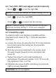
2.2 Turn ON / OFF and adjust red dot intensity • Press or to turn the sight ON. NOTE: The sight will always turn ON at setting 7 of 10. • Hold to turn the sight OFF. • Press or to adjust red dot intensity. NOTE: Intensity setting 1 - 2 are intended for use with NVD and intensity setting 3 - 10 for use in daylight. 2.3 Install the sight To install the sight to an interface compatible with the integrated mount shown in Fig.
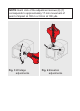
2.4 Zeroing CAUTION: Do not continue to adjust windage and elevation screws (6) (7) if you encounter resistance. a Adjust the intensity to a comfortable setting for the red dot to contrast clearly against the target. b Use the Torx T10 of the Aimpoint tool (8) to turn the adjustment screws (6) (7). c Windage adjustments (see Fig. 3): • Turn windage adjustment screw (6) counterclockwise to move point of impact to the right (R). • Turn windage screw (6) clockwise to move point of impact to the left.
NOTE: Each click of the adjustment screws (6) (7) corresponds to approximately 17 mm movement of point of impact at 100 m or 0.6 in at 100 yds. Fig. 3 Windage adjustments Fig.
3 EXTREME CONDITIONS • Extreme heat (moist or dry): no special procedures required. • Extreme cold: extreme cold might shorten battery life. • Salt air: no special procedures required. • Sea spray, water, mud and snow: ensure the battery cap (3) is tightened before exposing the sight to sea spray, mud, snow or before submerging the sight in water. Clean lenses with lens paper/cloth and wipe the sight dry as soon as possible after exposure to water, sea spray, mud or snow.
4 TROUBLESHOOTING The red dot does not appear or has disappeared Make sure contact surfaces in the battery compartment are clean and verify that a working battery (CR1225) is installed correctly according to 2.1. If the sight is malfunctioning, notify local dealer/armourer. The sight is impossible to zero If an adjustment screw (6) or (7) is at its limit, check the alignment of mount and barrel.
Aimpoint AB Jägershillgatan 15 SE- 213 75 Malmö, Sweden Phone: +46 (0)40 671 50 20 Fax: +46 (0)40 21 92 38 e-mail: info@aimpoint.se Aimpoint Inc. 7309 Gateway Court Manassas, VA 20109, USA Phone: +1 703-263-9795 Fax: +1 703-263-9463 e-mail: info@aimpoint.com WWW.AIMPOINT.COM © 2019 Aimpoint AB.