LCU-ONE CAN + Analog User Manual
LCU ONE-CAN+Analog User manual Release 1.05 INDEX 1 – LCU-ONE CAN + Analog description ..................................................................... 2 2 – LCU-ONE mounting ................................................................................................. 3 3 – LCU-ONE power ....................................................................................................... 3 4 – Lambda probe mounting..................................................................................
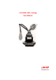
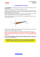
LCU ONE-CAN+Analog User manual Release 1.05 0 1 – LCU-ONE CAN + Analog description LCU-ONE CAN+Analog (from here onward LCU-ONE) is a lambda controller for wide band BOSCH LSU 4.9 lambda probe. It fits petrol and diesel engines as well as alcohol based fuel engines. It is intended to check lambda probe proper working as well as to transmit Air/Fuel Ratio values or Lambda values both through the CAN bus or through a serial RS232 bus.
LCU ONE-CAN+Analog User manual Release 1.05 1 2 – LCU-ONE mounting Install LCU-ONE in a flat location and far from heat sources. Install it steady using the lateral fixing holes. Arrange the wiring in the engine compartment or in the cockpit paying attention not to let them pass close to heat sources. If using the CAN bus, remember that CAN cable needs to be terminated with an appropriate resistance. This is why the kit includes the terminator inserted in the Deutsch connector plug.
LCU ONE-CAN+Analog User manual Release 1.05 2 4 – Lambda probe mounting Install LCU-ONE in a flat location and far from heat sources; install it steady using the supplied bracket. Arrange the wiring so to avoid it passing close to heat sources. BOSCH LSU 4.9 Lambda probe is to be installed on the vehicle exhaust pipe using a specific adaptor supplied with the kit and is to be welded on the same pipe. The probe should be sufficiently near to the engine.
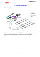
LCU ONE-CAN+Analog User manual Release 1.05 3 9 5 – LCU-ONE connection 5.1 – Analog Connection Refer to the image above to make an LCU-ONE analog connection. Extensions labelled as “3” and “4” are to be used to interface LCU-ONE with AIM loggers, while extension labelled as “5” is to be used for serial programming. Refer to this tutorial appendix for items part numbers and connectors pinout. www.aim-sportline.
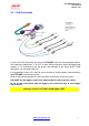
LCU ONE-CAN+Analog User manual Release 1.05 15 5.2 – CAN Connection In case of a CAN connection with only one LCU-ONE, follow the scheme shown above. Use extensions labelled as “1” and “2” to make CAN connections with AIM loggers that support it. It is reminded to use the proper cap indicated in the figure above (“CAN termination”) to terminate CAN line. It is suggested to insert a 5 A fuse for each controller in series between external battery and LCU-ONE to protect the system.
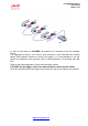
LCU ONE-CAN+Analog User manual Release 1.05 In case of more than one LCU-ONE, the scheme to be followed is the one indicated above. It is suggested to insert a 10 A fuse for each controller in series between the external battery and Lambda controller to protect the system. It is recommended to use the proper cap indicated in the previous figure (“CAN termination”) to terminate the CAN line. Refer to this tutorial appendix to know each item part number.
LCU ONE-CAN+Analog User manual Release 1.05 4 6 – LCU-ONE Configuration To work properly LCU-ONE needs to be configured for both the CAN part and the analog part. In case Race Studio 2 software is available it is possible to use it to completely configure LCU-ONE. In case the only analog configuration is needed, follow this instruction. 10 6.
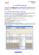
LCU ONE-CAN+Analog User manual Release 1.05 Set the probe configuration panel that appears bottom on the left of channel layer, highlighted in the figure here below. Activate the drop down menu pressing the button green circled in the figure here above and select the type of fuel used by the vehicle. www.aim-sportline.
LCU ONE-CAN+Analog User manual Release 1.05 In case the used fuel is not included in the database (and only in case its Stoichiometric value is known) press “Add custom value” button and the window here below appears. Fill in the new value and its legend. Press “Add new item to” button and then “Save” button. The fuel is now available in the drop down menu: select it. www.aim-sportline.
LCU ONE-CAN+Analog User manual Release 1.05 16 6.2 – LCU-ONE Analog custom configuration In case calibration curve default points have been changed it is necessary to configure LCU-ONE analog part using Lambda Configurator, the software properly designed and developed by AIM to manage this device and freely downloadable from AIM website www.aim-sportline.com. Warning: to correctly configure the controller, ensure that Lambda Configurator is 1.00.07 or later.
LCU ONE-CAN+Analog User manual Release 1.05 20 6.2.1 – Preliminary operation Lambda Configurator software, differently from other AIM software, includes a firmware version of the logger it configures. This is why it is suggested to always check www.aim-sportline.com to know if the software version installed on the PC is the last available.
LCU ONE-CAN+Analog User manual Release 1.05 The first operation to perform is selecting the used fuel in the pop up menu of “Multiplier to calculate AFR from Lambda” panel shown below or insert a new multiplier following the procedure here explained. In case the used fuel Is not included in the database (and only in case its Stoichiometric value is known) press “Add custom value” button and the window shown below appears. Insert the new value and the related legend.
LCU ONE-CAN+Analog User manual Release 1.05 Afterwards operate on the other parameters. “Use: Lambda/AFR” these buttons allow the user to decide if showing Lambda values or AFR (Stoichiometric values). This choice reflects on the layout of the panel, as shown below: The coloured button beside the cases indicates the colour this value is drawn in the central graph (in the example the value is shown in light blue).
LCU ONE-CAN+Analog User manual Release 1.05 21 6.2.3 – The keyboard On the left of the window are some buttons: • • • • “Restore default lambda settings”: allows the user to restore default settings on LCU-ONE. “Transmit lambda configuration”: allows the user to transmit the configuration to the device “Read lambda configuration”: reads the configuration from a logger “Upgrade Firmware”: allows the user to update controller firmware.
LCU ONE-CAN+Analog User manual Release 1.05 22 6.2.4 – Informative panels Top left of the software main window, a series of panels shows some information concerning the connected LCU-ONE. These panels layout changes depending on the fact that the logger is connected or not. The figure below shows panels layout with LCU-ONE connected on the left and with the controller not connected on the right.
LCU ONE-CAN+Analog User manual Release 1.05 23 6.2.5 – The analog output graph The “analog output graph” shows output tension values of the controller that refer to measured Lambda (or AFR) values. Graph colours can be changed. Pressing “Colour options” button top on the right and this window appears: Pressing each button a colour choice panel appears showing the available colours for that graph characteristic. Selecting the desired colour and confirming the choice the graph layout changes. www.
LCU ONE-CAN+Analog User manual Release 1.05 24 6.2.6 – Online values from Lambda controller. This panel shows the controller status and allows the user to set only Lambda/AFR and temperature unit of measure for the shown values. www.aim-sportline.
LCU ONE-CAN+Analog User manual Release 1.05 17 6.3 – LCU-ONE CAN configuration As said before, LCU-ONE can communicate using the CAN bus too and this type of communication allows it to interface with AIM MXL/EVO3. To better profit by this channel it is necessary to configure the controller with Race Studio 2 software. Refer to the related user manual for further information on the software and to the loggers user manual for further information on these latter and their configuration.
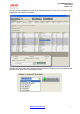
LCU ONE-CAN+Analog User manual Release 1.05 The layer is modified as shown below and as many additional layers as many Lambda probe have been added appear. In case serial number has not been get, press “Get serial number from a connected expansion” button. Warning: this operation is necessary to transmit the configuration to the controller. The layer concerning the probe is shown above. Top Fields “Name of expansion configuration (6 characters max)” and “Serial number of expansion”.
LCU ONE-CAN+Analog User manual Release 1.05 Central in the page a table made of 7 columns shows the controller channels. Enabled/disabled: shows channel status (enabled/disabled). It can be modified checking or un-checking the related checkbox. LCC_lambda (Lambda value) and LCC_AFR (AFR value) channels are enabled by default. Channel name: shows the name of the channel and can be modified double clicking on the cell, that becomes editable.
LCU ONE-CAN+Analog User manual Release 1.05 Under the table is “Multiplier to calculate AFR from lambda” field. It allows to both change used fuel and insert a new one. Select the used fuel to show AFR. In case used fuel is not included in the database and only in case its Stoichiometric value is known press “Add custom value” button and the figure below appears. Insert the new value and the related legend. Press “Add new item to list” button and then “Save” button.
LCU ONE-CAN+Analog User manual Release 1.05 Once enabled/disabled the channels it is possible to decide which channel to show on the display depending on the logger and on the connected peripherals. In case of an MXL it is possible to show the channels setting them in “System configuration” layer. In this example enabled channels are LCC_Lambda, LCC_AFR and LCC_diagnosis. As shown below each channel can be set in a display field.
LCU ONE-CAN+Analog User manual Release 1.05 In case of an EVO3 data visualisation is only possible if the logger is connected to a Formula Steering Wheel or to a MyChron3 Dash and they are set on that display configuration as shown below. Note: LCC_diagnosis channel shows the probe working status and can show up to four messages: • • • • 0: status OK 1: probe not connected 2: + 12 V short circuit 3: GND short circuit The configuration is now ready to be transmitted to the logger.
LCU ONE-CAN+Analog User manual Release 1.05 5 11 7 – Data visualisation on MXL/EVO3 7.1 – Data visualisation on MXL The visualisation of Lambda channels on MXL works like the visualisation of any other channel and switch from one page to the other of the display is made through “MEM/View” button. Refer to MXL user manual for further information. In the image below Lambda value is 0.955 and channel name is LAM.
LCU ONE-CAN+Analog User manual Release 1.
LCU ONE-CAN+Analog User manual Release 1.05 7 13 Appendix – Part numbers and technical drawings “A” – Part number of LCU-ONE CAN+Analog complete kit WARNING: each kit contains one only extension for each communication protocol and depending on the connector (plastic or metallic) that is wished on the wiring and that is in any case included in the kit, kit part number is going to change following this table. LCU-ONE CAN+Analog complete kit includes: LCU-ONE CAN+Analog Bosch LSU 4.
LCU ONE-CAN+Analog User manual Release 1.05 18 “C” – Technical drawings www.aim-sportline.
LCU ONE-CAN+Analog User manual Release 1.05 N.rev. / Rev. N. Descrizione / Description Data / date Firma / Sign Contr. da / Ckd. by PINOUT LCU-ONE CAN+Analog 6 5 4 3 2 12 11 10 9 1 8 7 18 17 16 15 14 13 16 pin AMP male connector pinout 1 2 3 4 5 6 7 8 9 Rif. / Ref. Q.tà / Q.ty Progettato da / Designed by GND (power) +V batt HIP-/VSVS+ RS232RX PC +VB GND (CAN) H+ 10 11 12 13 14 15 16 17 18 Rcal IP+ RS232TX PC CAN+ CANnc GND (signal) Lambda Out GND (RS232) N. articolo / Item N.
LCU ONE-CAN+Analog User manual Release 1.05 Firma / Sign Contr. da / Ckd.
LCU ONE-CAN+Analog User manual Release 1.05 N.rev. / Rev. N. Descrizione / Description Firma / Sign Contr. da / Ckd.
Lambda out GND nc nc 1 2 3 4 Lambda out GND nc nc 1 2 3 4 Binder connector pinout Deutsch connector pinout 4 pins Binder 712 male connector pinout Contacts insertion view 4 pins Deutsch female connector pinout Contacts insertion view 2 3 3 1 2 4 1 4 4 pins Deutsch female connector Analog connection cable for LCU-ONE CAN+Analog metallic Binder 4 pins Binder 712 male connector LCU ONE-CAN+Analog User manual Release 1.05 Rif. / Ref. Q.tà / Q.ty Progettato da / Designed by N. articolo / Item N.
LCU ONE-CAN+Analog User manual Release 1.05 CAN termination cap pinout 6 6 pins Deutsch male connector 2 120 1 3 5 4 6 pins Deutsch male connector pinout Contacts insertion view Note: there is a 120 Ohm resistance between pins 1 and 4 of the connector Rif. / Ref. Q.tà / Q.ty Progettato da / Designed by N. articolo / Item N. Materiale / Material Contr. da / Ckd. by Approvato da / Approved by Nome file / File name Data / Date Scala / Scale L.I. Titolo / Title N. disegno / Drawing N.
LCU ONE-CAN+Analog User manual Release 1.05 N.rev. / Rev. N. Descrizione / Description Firma / Sign Contr. da / Ckd.
LCU ONE-CAN+Analog User manual Release 1.05 N.rev. / Rev. N. Descrizione / Description Firma / Sign Contr. da / Ckd.