
Instructions


21
Changing the load mode while the input is enabled will trip a fault detector and cause the input to
be disabled before the change is implemented.
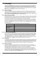
7.6 Selection of Load Mode
The first action in configuring the unit for a particular application is to choose the load mode,
which determines how the current drawn by the load varies with the applied voltage (V). The
Mode soft-key on the home screen opens a menu offering the various modes listed in the table
below. More detailed descriptions of the properties of each mode are given in the ‘Application
Notes’ section 9.
Changing the mode requires the load input to be disabled, which will be done automatically if not
already done by the user. The display returns to the home screen as soon as a mode is selected.
The available operating modes are:
CC
Constant Current
The current is the Level setting, independent of voltage.
CP
Constant Power
Implements I = W / V where W is the Level setting.
CG
Constant Conductance
Implements I = V * G where G is the Level setting.
CR
Constant Resistance
Implements I = (V – V
dropout
) / R where R is the Level setting
and V
dropout
is the Dropout Voltage setting.
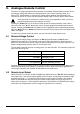
7.7 Level A and Level B Setting
Pressing the Level soft-key on the home screen initially opens the level setting prompt for either
Level A or Level B, depending on which was altered last. The right hand soft-keys, labelled
A SET and B SET, can be used to switch the prompt to the other level. If the level being edited is
not currently active in controlling the load, a Select soft-key will appear allowing it to be made the
active selection if required. A new numeric value can be entered as described above. Separate
settings for both level values are retained for each operating mode.
The level setting menu remains on screen, allowing further changes to be made, until either the
Back soft-key or the
Home key is pressed to return to the home screen.
7.8 Dropout Voltage
Pressing the Dropout soft-key on the home screen opens the Dropout Voltage setting prompt. In
the usual way this displays the present Dropout Voltage setting, the range in which the new value
can be set, and the maximum resolution of the setting. After entry of the number press either the
mV or V soft-key to implement the setting. Either the Back soft-key or the
Home key returns the
display to the home screen.
The primary purpose of the dropout voltage setting is to protect batteries from excessive
discharge. The load will cease to conduct current when the applied voltage from the source falls
below this setting. Note that this is a dynamic limit, not a latching condition, so if there is any
wiring resistance between the source and the voltage sensing point of the load then there will be
a soft entry into the dropout condition – the series voltage drop will reduce as the current starts to
fall, so raising the voltage measured by the load. Batteries may also recover as the load is
reduced, raising the voltage back above the dropout threshold so the load resumes conduction.
There is a possibility of hunting or instability in this operating condition. The front panel lamp will
show yellow and the status line report Dropout when the dropout circuit becomes active.
The Dropout Voltage setting has a special effect in Constant Resistance (CR) mode, when it
provides a starting point for the constant resistance characteristic (see the description in the
‘Application Notes‘ chapter for more detail).
The Dropout Voltage setting is also used as the threshold for the Slow Start circuit (see below).
If the dropout facility is not required, set the Dropout Voltage to 0 Volts. The status line will show
Dropout as a warning whenever this setting is above 0V and no current is being drawn.