
Instructions


17
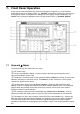
7. Front Panel Operation
In this manual, front panel labels are shown as they appear, in capitals, e.g. LEVEL SELECT.
Individual key names are shown in bold, e.g.
Transient, and the blue soft-keys are referred to by
their present function, as labelled on the bottom line of the display, shown in bold italics, e.g.
Limits. Text or messages displayed on the LCD are shown in bold, e.g
. Enabled, Utilities.
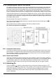
7.1 Keys and ∆ Adjust
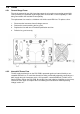
The front panel keys are divided into four areas:
① The numeric keys.
② The blue keys below the display - Used to configure the instrument through the menu
structure described in section 7.2.4.
③ The
CE key - Cancels the last numeric keystroke while the Home key cancels an entire menu
selection and returns to the home screen. The
Home key is also used for the ‘return to local’
request from digital remote control.
④ The three
LEVEL SELECT keys (A, B and Transient) - Determine which of the two level
settings is active, or engage the transient mode which switches between them. The associated
lamps indicate the presently active state; these keys are also used to return from external
analogue control to manual selection.
⑤ The
∆ ADJUST knob and its three associated keys (Levels, Off and Transient) - Used to
choose and modify the existing value of any one of the numeric parameters of the instrument.
⑥ The
ENABLE key in the INPUT section (referred to as the INPUT ENABLE key) - Controls the
load, with alternate presses switching between the conducting and non-conducting conditions.
The green lamp shows if the input is enabled; the yellow lamp reports if the power stage is
saturated, as described in the paragraph ‘Input Condition Lamps’ in the ‘Initial Operation’ section
6.8.