
Instructions


16
6.10 Connecting the Load to the Source
The INPUT terminals of the load must be connected to the source to be tested using sufficiently
low resistance and low inductance connections. Inductance in the interconnection can have a
significant adverse impact on the stability of the source and load combination. The wiring should
be as short and as thick as possible. It is essential that the voltage drop across the connecting
leads is sufficiently less than the source voltage to leave enough working voltage across the load.
The load input terminals of the instrument are floating from ground, and are rated to CATII 300V.
Connection to an AC mains circuit, primary side DC or non isolated bridge rectifier is permitted on
the negative input terminal with a voltage limit of 500Vdc between the positive input terminal and
the negative input terminal.
Reverse polarity of the inputs is not permitted.
The maximum permissible voltage between the negative input terminal and earth ground
is
425V (peak of CAT II 300V).
Ensure that all wiring is safely insulated for the working voltage involved.
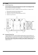
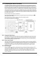
PFC safe test and operation area diagram
6.10.1 Prospective Fault Current
The instrument detects any fault condition and responds by disabling the load by turning off the
power devices. As a last resort there are internal fuses in the load circuit, so that if the external
source applies a condition so far beyond the current rating of the unit, the fuses will protect the
instrument against dangerously high currents.
6.10.2 Remote Input Disable
This input is provided for remote override of the INPUT ENABLE function of the load, possibly for
safety reasons. It is available in all operating modes of the instrument. It is a fully floating input to
an opto-isolator: apply 3 to 12 volts (observing polarity) to disable the load. The load is only
enabled if this signal is absent and the input has been enabled with the front panel controls.
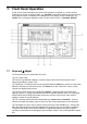
6.11 Switching On
The line POWER ( ) switch is at the bottom left of the front panel. Before switching on ( l ),
check that the line operating voltage of the unit (marked on the rear panel) is suitable for the local
supply. After switching the power on (
l ) the LCD should light and display firmware version
information. Avoid turning off the power until the instrument is fully initialised and the home
screen is displayed.