
Instructions


13
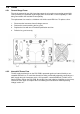
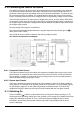
5.2.2.2 Oscillator Sync Output
The SYNC OUTPUT is a TTL/CMOS (5V) output driven by the signal from the internal oscillator;
this output is chassis ground referenced. There is a 1kΩ series protection resistor.
5.2.2.3 Remote Control Voltage Input
The CONTROL VOLTAGE terminals are used in two operating modes of the instrument:
In EXTERNAL VOLTAGE mode an analogue signal applied here sets the level of the load; the
scaling is 4 Volts full scale.
In EXTERNAL TTL mode, a logic signal applied here selects either the LEVEL A setting (logic
low) or the LEVEL B setting (logic high). The switching threshold is nominally +1·5V.
These terminals are referenced to chassis ground. Input impedance 10kΩ. Inputs are
protected against excess input voltages up to 50V.
5.2.2.4 Current Monitor Output
The top pair of terminals, marked CURRENT MONITOR, provide the current monitor output.
They are wired in parallel with the front panel Current Monitor BNC and the same requirements
apply.
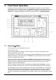
5.2.3 Digital Remote Control Connections
The LDH400P model provides full remote control capabilities through standard LAN, USB, GPIB
and RS232 interfaces. All of these are isolated from the load input terminals of the unit. The USB,
GPIB and RS232 interfaces are connected to chassis ground, and care must be taken to avoid
introducing ground loops. The LAN interface is isolated by standard network transformers.
Full details are given in the ‘Remote Interface Configuration’ section 10.
5.3 Prospective Fault Current Protection
This unit is not intended to act as an overcurrent fault protection device for the source being
tested. However the instrument does contain two 10A, 1000V, HRC fuses that protect the unit
against currents that exceed 20A. This is primarily as a protection against high power sources
with a current capability of >20A being connected to the load with reverse polarity, but will also
provide protection against any other prospective fault current >20A.