
Instructions


12
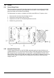
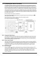
5. Connections
5.1 Front Panel Connections
5.1.1 Load Input
The INPUT terminals for the load circuit on the front panel accept 4mm plugs. Their maximum
current rating is 16 Amps.
Do not use both the front panel and rear panel terminals simultaneously.
The wiring and connection arrangement must be capable of supporting the current required.
The load circuit is isolated from ground, with a rating of CATII (300V), but it is essential to
observe safe insulation practice.
Ensure that the source is connected with the correct polarity.
The maximum current through these terminals is 16 Amps.
The maximum voltage allowed across the load is 500 Volts.
The unit contains a fuse in the load circuit, see section 4.5.
5.1.2 Current Monitor Output
The Current Monitor terminals provide a voltage proportional to the load current flowing with a
scaling factor of 250 mV per Amp (4 Volts for 16 Amps full scale). The output impedance is
nominally 600Ω and the calibration assumes a high impedance load such as an oscilloscope.
The current monitor circuit is referenced to chassis ground, as such is isolated from
the load circuit with a rating of CATII (300V).
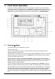
5.2 Rear Panel Connections
5.2.1 Load Input
The INPUT terminals for the load circuit on the rear panel accept 4mm plugs. Their maximum
current rating is 16 Amps.
Do not use both the front panel and rear panel terminals simultaneously.
The wiring and connection arrangement must be capable of supporting the current required.
The load circuit is isolated from ground, with a rating of CATII (300V), but it is essential to
observe safe insulation practice.
Ensure that the source is connected with the correct polarity.
The maximum current through these terminals is 16 Amps.
The maximum voltage allowed across the load is 500 Volts.
The unit contains a fuse in the load circuit, see section 4.5.
5.2.2 Terminal Blocks
All other rear panel connections are made via the screw-less terminal blocks. To make
connections to the terminal blocks, use a flat screwdriver to press the spring-loaded orange
actuator inwards to open the wire clamp; insert the wire end fully into the hole and release the
actuator. Ensure the wire is properly gripped. Take care to observe the marked polarity.
5.2.2.1 Remote Disable Input
Apply greater than +3V (preferably +5V) to the DISABLE INPUT terminals to disable the load
input; these are the input to an opto-coupler, through 1kΩ, and are galvanically isolated from all
other terminals. The input current is less than 2·5mA at 5V.
The maximum input voltage is +12Vdc. Avoid reverse polarity.