
Installation Instructions

AI-NB25
NB-IoT Module
Sichuan AI-Link Technology Co.,Ltd. page 9 of 20
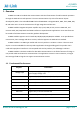
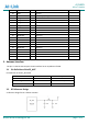
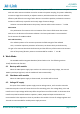
3.4 Antenna Reference Design
AI-NB25 module provide an RF antenna (pin2) pad for antenna connection. There are two grounding
Pads just as(pin1 & pin3 )on the both sides of the antenna pad in order to give a better grounding.
Besides, π-type match circuit is suggested to be used to adjust the balanced of Antenna RF performance,
and it is better to keep match circuit close to RF_ANT port of the module.
Fig. 4 Antenna matching circuit diagram
3.5 Antenna Design Indicators
Antenna Efficiency :
Antenna efficiency is the ratio of the input power to the radiated or received
power of an antenna. The radiated power of an antenna is always lower than the input
power due to the following antenna losses: return loss, material loss, and coupling loss.
The efficiency of an antenna relates to its electrical dimensions. The following antenna
efficiency (free space) is recommended for AI-NB25 module to ensure high radio
performance of the module:
Efficiency of the antenna: ≥ 40% (below 960 MHz); ≥ 50% (over 1710 MHz)
S11 (VSWR) :
S11 indicates the degree to which the input impedance of an antenna matches the
reference impedance (50 Ω). S11 shows the resonance feature and impedance bandwidth
of an antenna. Voltage standing wave ratio (VSWR) is another expression of S11. S11 is less
important than the efficiency, and S11 has weak correlation to wireless performance.
The following S11 value is recommended for the antenna of AI-NB25 module:
S11 of the primary antenna: ≤ –6 dB
Isolation