
Installation Instructions

AI-NB25
NB-IoT Module
Sichuan AI-Link Technology Co.,Ltd. page 10 of 20
For a wireless device with multiple antennas, the power of different antennas is coupled
with each other. Antenna isolation is used to measure the power coupling. The power radiated by
an antenna might be received by an adjacent antenna, which decreases the antenna radiation
Efficiency and affects the running of other devices. To avoid this problem, evaluate the antenna
isolation as sufficiently as possible at the early stage of antenna design.
Isolation recommended between the primary antenna and the other antenna: ≥15 dB
Polarization
The polarization of an antenna is the orientation of the electric field vector that rotates
with time in the direction of maximum radiation. The linear polarization is recommended
for the antenna of AI-NB25 module.
Gain and Directivity
The radiation pattern of an antenna represents the field strength of the radiated.
Gain, as another important parameter of antennas, correlates closely to the directivity.
The gain of an antenna takes both the directivity and the efficiency of the antenna into account.
Gain of the primary/diversity antenna recommended for module ≤ 2.5 dBi
4. Work Mode
The AI-NB25 module integrates baseband, RF and other units. The following sections
briefly describe each function
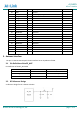
4.1 Boot up with module
When the VBAT power supply input reaches the minimum operating voltage, the external
RESET input keeps high level, and the module will start automatically.
4.2 Shut down with module
When the VBAT power supply is disconnected, the module will be closed.
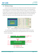
4.3 Voltage DC supply
The input of the module's power supply uses DC voltage source, and it needs to meet the
instantaneous peak current of 0.5A at the time of transmitting pulse. The voltage drop, noise and
interference in input voltage will directly affect the performance of the module. To eliminate these
interference, ESR low 100uF tantalum capacitors, 100nF, 100pF and 33pF combinations are
recommended. Filter capacitor as close as possible to the module. The use of voltage regulator and
TVS tube is recommended for module power supply entrance.