
Instructions / Assembly

23
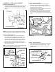
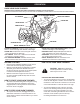
STEP 55: (SEE FIGURE 54)
• Placethesnowthroweronaat,levelsurface.
• RemovetheAttachmentPinfromthesnowthrower.
• Extendtheaugerbeltoutbehindthesnowthrower,
keepingthebeltassembledtothesnowthrowerpulleys.
• Rollthetractorupbehindthesnowthrower,centering
itbetweenthesnowthrower'smountingplates.
• Raisetherearofthesnowthrowerbyliftingupon
thelifthandleuntilthenotchesinthemountingplates
alignwiththeshoulderboltsinthetractor'sside
plates.Guidetheboltsintothenotches.
• Delayinstallingtheattachmentpinuntilyouhave
assembledthebeltasinstructedinsteps56and57.
ATTACHING SNOW THROWER TO TRACTOR
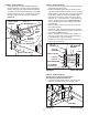
STEP 56: (SEE FIGURE 55)
• Theaugerbeltcomespreassembledtothepulleyson
thesnowthrowerhousing.Makesurethebeltpasses
over the top of the auger pulley and then twists 1/4
turn to pass underneath each side idler pulley. The
"V"sideofthebeltmustmatewiththegroovesofthe
pulleys.
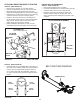
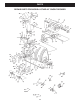
FIGURE 56 VIEWED FROM UNDERNEATH
CLUTCH/IDLER ASSEMBLY
INSTALLING THE AUGER BELT
STEP 57: (SEE FIGURE 56)
• Removetheattachmentpin,ifinstalled.
• Pushthelifthandledowntoincreaseslackinthebelt.
• Swingtheloweridlerarmovertotheleftside.
• Placetheaugerbeltaroundtherearpulleyand
betweenthetwopulleysontheidlerarm.The"V"
sideofthebeltmustbeseatedinthegroovesofthe
V-pulleys.
IDLER
PULLEY
AUGER PULLEY
TWIST
1/4 TURN
TWIST
1/4 TURN
IDLER
PULLEY
FIGURE 55
ATTACHMENT PIN
(After installing auger belt)
1/8" HAIRPIN
COTTER (EE)
SHOULDER
BOLT
MOUNTING
PLATE
SIDE PLATE
FIGURE 54 RIGHT SIDE VIEW
IDLER
ARM
REAR
PULLEY
LEFT SIDE
OF
TRACTOR
BELT ROUTING DIAGRAM
ENGINE PULLEY