
Instructions / Assembly


22
5/16" NYLOCK NUT (Y)
CHUTE CRANK
BRACKET
5/16" WASHER (Q)
CHUTE
CRANK
ROD
ROD
SUPPORT
BRACKET
5/16" x 1"
CARRIAGE BOLT (J)
SPIRAL
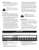
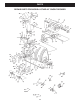
FIGURE 51 LEFT SIDE VIEW
FIGURE 52 RIGHT SIDE VIEW
CHUTE KEEPER (BB)
ANTI-ROTATION
BRACKET
1/4" FLANGED
LOCK NUT (V)
1/4" FLAT
WASHER (P)
1/4" x 1"
HEX BOLT (D)
PLASTIC CAP (HH)
GREASED
SURFACE
FLANGE
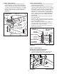
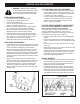
STEP 53: (SEE FIGURE 52)
• Coatthetopoftheringaroundthedischargeopening
with general purpose grease.
• Placethedischargechute(facingforward)ontothe
ring.Placetheanti-rotationbracketontopofthechute
ange,aligningitwiththeholesontherighthandside
oftheange.Attachthethreechutekeepers(BB)
(rightsideupasshown)tothebottomoftheange
usingsix1/4"x1"hexbolts(D),1/4"atwashers(P)
and1/4"angedlocknuts(V).Tighten carefully so
thatthenutsaresnugbutdonotdigintotheplastic
chutekeepers.
• Placetheplasticcap(HH)ontotheshortendofthe
anti-rotationbracket.
• Positionthecrankrodspiral(seegure51)sothatit
doesnotrubagainstthebottomsofthenotchesinthe
chuteange.Tighten the nuts.
• Checkifthecrankrodrotatesthechutefreely.Ifnot,
loosenby1/4turneachofthesixhexboltsholding
thechutekeeperstothechuteange.
• Securethecontrolcablestothecrankrodsupport
tubeusinganylontie(II).
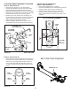
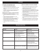
STEP 54: (SEE FIGURE 53)
Skip this step if you have a lawn tractor.
This step is for garden tractors only.
• Ifyouhavea(GT)GardenTractor,removethestop
boltsfromeachsideofthesnowthrowerframe.
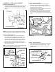
STEP 52: (SEE FIGURE 51)
• Attachthechutecrankrodassemblybracketsto
theplasticbracketontheleftsideofthedischarge
housing.Alignthechutecrankbracketbeneaththe
rodsupportbracketandassemblebothtotheplastic
bracketusingtwo5/16"x1"carriagebolts(J),5/16"
washers(Q)and5/16"Nylocknuts(Y).Do not
tighten yet.
STOP BOLT
FIGURE 53 RIGHT SIDE VIEW