
Instructions / Assembly


21
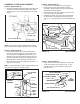
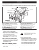
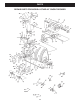
STEP 48: (SEE FIGURE 47)
• Placethelifthandleintotheliftbracketontherightside
ofthesnowthrower.Fastenthehandletothebracket
usingtwo5/16"x1-3/4"hexbolts(B)and5/16"Nylock
nuts (Y).
FIGURE 48 RIGHT SIDE VIEW
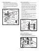
NOTE:Besuretheliftreleasecable'splasticcovering
staysinsertedintothetriggerassemblyforthenextstep.
STEP 49: (SEE FIGURE 48)
• Pushthelifthandledownintothelockedposition.
Inserttheendofthecablewireintotheholeinthe
liftrod.Placethethreadedttingintotheslotinthe
liftbracket,withonehexnutaboveandonehexnut
andthelockwasherbelowtheslot.Tightenthenuts,
adjustingthemtoeliminateslackinthecablewire.
ReferalsototheServiceandAdjustmentssectionon
page27inthismanual.
HINT: Foreasierassemblyoftheliftreleasecable,tiltthe
snow thrower forward onto the spiral auger.
FIGURE 47 RIGHT SIDE VIEW
5/16" NYLOCK NUT (Y)
5/16" x 1-3/4"
HEX BOLT (B)
ASSEMBLY OF THE SNOW THROWER
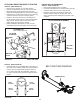
STEP 50: (SEE FIGURE 49)
• Tiltthesnowthrowerbackdowntotheground.
• Removethenylontiewhichfastenstheauger
drivebelttothedischargehousing,leavingthebelt
assembledaroundthepulleys.
• Removethenylontiewhichfastensthechutecrank
rodtothecrankrodsupporttube.
• Assemblethecrankrodsupporttubetothebracket
on the left side of the discharge housing using two
5/16"x1-1/4"carriagebolts(I),and5/16"Nylocknuts
(Y).
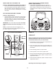
FIGURE 50 LEFT SIDE VIEW
STEP 51: (SEE FIGURE 50)
• Attachthechutetiltcontrolassemblytothetopside
ofthecranksupporttubeusingtwo5/16"x1-3/4"
carriagebolts(H),bowedwashers(U)and5/16"
Nylocknuts(Y).
5/16" NYLOCK NUT (Y)
5/16" x 1-1/4"
CARRIAGE BOLT (I)
CRANK ROD
SUPPORT TUBE
DISCHARGE
HOUSING
FIGURE 49 LEFT SIDE VIEW
CHUTE CRANK ROD
CRANK SUPPORT TUBE
TILT CONTROL HANDLE
5/16" x 1-3/4"
CARRIAGE BOLT (H)
BOWED WASHER (U)
5/16" NYLOCK NUT (Y)
TILT
CONTROL
ASSEMBLY
LIFT RELEASE
CABLE
HEX NUT
LOCK
WASHER
HEX NUT
CABLE
WIRE
LIFT
ROD
TRIGGER
ASSEMBLY