
Instructions / Assembly

16
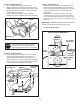
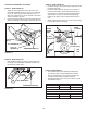
FIGURE 33 RIGHT SIDE VIEW
FIGURE 32 RIGHT SIDE VIEW
PIVOT LOCK PIN (GG)
(use second hole)
1/8" HAIRPIN COTTER (EE)
ENGAGEMENT
ROD
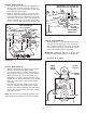
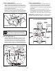
STEP 33: (SEE FIGURE 33)
• Makesuretheattachmentclutchleveronthedash
panel is in the disengaged (down) position.
• Pivottheupperidlerarmsothatitrestsagainstthe
stopboltandispointingtowardthefrontasshown.
Screw the trunnion (CC) along the threads of the
engagementroduntilitisalignedatthefrontendof
theidlerarmslot.Attachthetrunnion(CC)totheslot
using the 3/8" thin washer (S) and a 5/64" hairpin
cotter (DD).
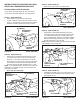
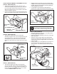
• Removetheenginepulleykeeperfromthesideof
thetractorframebyremovingthewasherandnut
thatsecurethekeeper.Attachthenewpulleykeeper
supplied with the snow thrower, reusing the original
bolt,washerandnut.
NOTE:Sometractorsmayalreadybeequippedwitha
pulleykeeperthatisidenticaltothenewonesupplied.
IDLER ARM
5/64" HAIRPIN
COTTER (DD)
TRUNNION (CC)
STOP BOLT
3/8" THIN
WASHER (S)
NEW ENGINE PULLEY KEEPER WITH
ORIGINAL BOLT, NUT AND WASHER
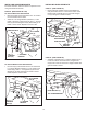
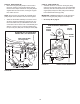
STEP 34: (SEE FIGURE 34)
• Assembletheshort"V"beltontotheenginepulley
and then onto the large pulley on top of the clutch/
idlerassembly.Thebeltmustbeplacedtotheinside
oftheenginepulleykeeper,theidlerpulleyandthe
keeperboltlocatedbesidethelargepulley.
IMPORTANT: Do Notassemblethe"V"beltaroundthe
outsideoftheenginepulleykeeperorthekeeperbolt.
• Go to step 48 on page 21.
FIGURE 34 VIEWED FROM UNDERNEATH
ENGINE
PULLEY
KEEPER BOLT
IDLER
PULLEY
ENGINE
PULLEY
KEEPER
Left Side
of Tractor
CLUTCH/IDLER ASSEMBLY
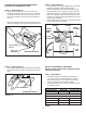
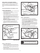
STEP 32: (SEE FIGURE 32)
• Besuretoliftupthefrontendoftheengagementrod
asshownwhenperformingthenextoperation.You
cantemporarilysupporttherodusingarubberband
tiedtotheenginepulleykeeper.
• Attachtheclutch/idlerassemblytothetractorframe
asfollows.Hooktheassembly'snotchedarmsonto
thetwoshoulderboltsyouassembledtotheinside
ofthetractorframe.Liftthefrontoftheassemblyand
attachittotheR.H.andL.H.hangerbracketsusing
twopivotlockpins(GG)and1/8"hairpincotters(EE).