
Instructions / Assembly

14
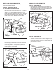
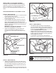
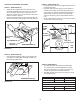
FIGURE 28 RIGHT SIDE VIEW
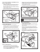
INSTALLING HANGER BRACKETS
Forbetterclearance,lowerthetractor'ssuspensionarms
usingtheattachmentliftlever.
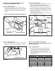
STEP 26: (SEE FIGURE 25 or 26)
On Tractors With Foot Rest Brackets
• RemovetheboltandnutthatfastentheL.H.andR.H.
footrestbracketstotheframe.
• AttachtheL.H.HangerBracket(marked"L")tothe
insideofthetractorframeusingtwo3/8"x1"carriage
bolts(G)and3/8"angednuts(X).Boltheadsgoon
insideoftractorframe.RepeatfortheR.H.side.
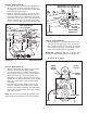
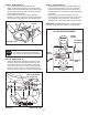
FIGURE 26 LEFT SIDE VIEW
FIGURE 25 LEFT SIDE VIEW
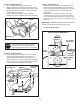
On Tractors Without Foot Rest Brackets
• Findtheemptyholebeneaththefootrest.Attachthe
L.H.HangerBracket(marked"L")totheinsideofthe
frameusinga3/8"x1"carriagebolt(G)anda3/8"
angednut(X).Boltheadgoesoninsideoftractor
frame.RepeatfortheR.H.side.
STEP 28: (SEE FIGURE 28)
• Assembleashoulderbolt(L)and3/8"angednut(X)
totheR.H.sideofthetractorframe,usingtherst
emptyholetotherearoftheR.H.hangerbracket.Bolt
goesoninsideofframe.
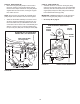
FIGURE 27 LEFT SIDE VIEW
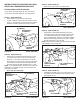
INSTALLING SHOULDER BOLTS
STEP 27: (SEE FIGURE 27)
• Removethebolt,washerandnutwhichfastenthe
swaybarbrackettotheL.H.sideofthetractorframe.
Replacewithashoulderbolt(L)anda3/8"anged
nut(X).Boltgoesoninsideofframe.
BOLT REMOVED
FROM THIS HOLE
SWAY BAR
BRACKET
SHOULDER BOLT (L)
3/8"
FLANGED
NUT (X)
3/8" x 1"
CARRIAGE
BOLT (G)
3/8" FLANGED
NUT (X)
L.H. HANGER
BRACKET
SUSPENSION ARM
SHOULDER BOLT (L)
3/8"
FLANGED
NUT (X)
R.H. HANGER BRACKET
BOLT REMOVED
FROM THIS HOLE
3/8" x 1"
CARRIAGE
BOLT (K)
3/8" FLANGED
NUT (X)
L.H. HANGER
BRACKET
SUSPENSION ARM