
Instructions / Assembly

13
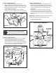
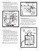
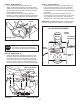
STEP 22: (SEE FIGURE 21)
• FastentheR.H.SidePlate(bendfacingout)tothe
frontthreeholesshowninthetractorframeusing
three3/8"x1"threadformingbolts(E),three3/8"
lockwashers(O)andone1/2"washer(R)placedon
thethirdboltasashimbetweenthesideplateand
theframe.Tightenallbolts.RepeatfortheL.H.side.
NOTE:Ifyouinstalledaboltinthefourthholeinstep21,
assemblea5/16"angenut(W)ontotheboltafterthe
side plate is installed.
• Go to step 25 on this page.
(3) 3/8" x 1"
THREAD FORMING
BOLTS (E)
5/16" FLANGED
NUT (W)
(SEE NOTE)
(3) 3/8" LOCK
WASHERS (O)
1/2" WASHER (R)
5/16" x 1"
CARRIAGE BOLT (J)
(SEE NOTE)
FIGURE 21 RIGHT SIDE VIEW
FRONT SUSPENSION
BRACKET
REMOVE BOLTS
IF PRESENT
FIGURE 22 RIGHT SIDE VIEW
STEP 23: (SEE FIGURE 22)
• Removeanyboltsfoundintheholesshown.
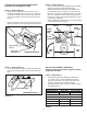
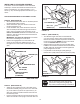
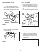
STEP 21: (SEE FIGURE 20)
• Removeboltsfromfrontthreeholesshown.
• Ifaboltispresentinthefourthhole,replaceitwitha
5/16"x1"carriagebolt(J)withoutanut.Thebracket
fastenedtoinsideofframemustremaininplace.
FRONT
SUSPENSION
BRACKET
REPLACE BOLT
(IF PRESENT)
REMOVE BOLTS
(IF PRESENT)
FIGURE 20 RIGHT SIDE VIEW
INSTRUCTIONS FOR TRACTORS WITH DUAL
FRONT DECK SUSPENSION BRACKETS
FASTEN SIDE PLATES TO TRACTOR
Ifyourtractorresemblesgure20,startwithstep21.
Ifyourtractorresemblesgure22,startwithstep23.
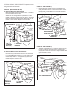
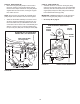
STEP 25: (SEE FIGURE 24)
• Assembleashoulderbolt(L)anda3/8"washer(T)to
theoutsideofeachsideplate,securingthemwitha
3/8"angednut(X).
FIGURE 24 RIGHT SIDE VIEW
3/8" WASHER (T)
SHOULDER
BOLT (L)
3/8" FLANGED
NUT (X)
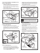
STEP 24: (SEE FIGURE 23)
• FastentheR.H.SidePlate(bendfacingout)tothe
threeholesshowninthetractorframe.Usethree3/8"
x1"threadformingbolts(E),3/8"lockwashers(O)
and1/2"washers(R).Usethe1/2"washersasshims
betweentheSidePlateandthetractorframe.Tighten
allboltsandrepeatfortheL.H.side.
NOTE:Iftheboltinsertsfreelyintothefronthole,assemble
a3/8"angednut(X)ontothebolt.
(3) 3/8" x 1"
THREAD FORMING
BOLTS (E)
(3) 3/8" LOCK
WASHERS (O)
3/8" FLANGED NUT (X)
(SEE NOTE)
(3) 1/2" WASHERS (R)
FIGURE 23 RIGHT SIDE VIEW