
Instructions / Assembly

11
THIS SECTION IS FOR TRACTORS WITH AN
ELECTRIC ATTACHMENT CLUTCH
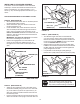
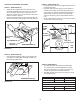
STEP 14: (SEE FIGURE 14)
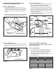
• Attachthetwosuspensionarmstotherearofthe
clutch/idlerassemblyusingtwo5/16"x3/4"hexbolts
(C)and5/16"nylocknuts(Y)foreacharm.Placethe
armsontheoutsideoftheframewiththenotchesto
the rear.
• Insertatensioningchainthroughtheholeshownand
attachtheendlinktothespringontheloweridlerarm.
FIGURE 14
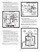
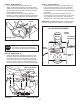
FIGURE 16 VIEW OF BOTTOM
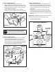
STEP 16: (SEE FIGURE 16)
• Hookoneendofthespringsuppliedinthepartsbag
throughtheendlinkofthetensioningchain.
• Withtheclutch/idlerassemblyturnedupsidedown,
hooktheotherendofthespringontotheendofthe
boltandnutwhichsecuretheidlerpulleytotheupper
idlerarm.Assemblea3/8"hexlocknut(Z)ontothe
boltandnut,leavingenoughgapbetweenthenutsfor
the spring to pivot freely.
• Attacha3/32"hairpincotter(FF)tothechain,placing
itinthefthlinkfromthespring.
CHAIN
(L.H. SIDE)
3/32" HAIR
COTTER PIN (FF)
5TH LINK
LEFT
SIDE
3/8" HEX
LOCK NUT (Z)
SPRING
RIGHT
SIDE
ATTACH
SPRING
HERE
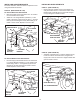
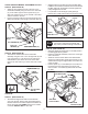
STEP 15: (SEE FIGURE 15)
• Turntheclutch/idlerassemblyupsidedownandplace
the second tensioning chain (JJ) through the left front
hole.
FIGURE 15
TENSIONING CHAIN (JJ)
LEFT FRONT HOLE
STEP 17: (SEE TABLE 1)
• Twodifferentlengthdrivebeltsareincludedwith
yoursnowthrower.Usethetablebelowtoselect
thecorrectdrivebeltforyourtypetractor.Thepart
numberisprintedontheoutsideofthebelt.
• Setasidethebeltthatisnotforyourtractortoavoid
accidentally using it.
SELECT THE CORRECT DRIVE BELT
(Electric clutch tractors with a single front deck
suspension bracket)
55" BELT (PART #46989)
TRACTOR TYPE DECK SIZE CLUTCH TYPE
(LT) Lawn Tractor 38", 42" Electric
56" BELT (PART #48138)
TRACTOR TYPE DECK SIZE CLUTCH TYPE
(LT) Lawn Tractor 48" Electric
(GT) Garden Tractor 48", 54" Electric
TABLE 1
5/16" NYLOCK
NUT (Y)
5/16" x 3/4"
HEX BOLT (C)
TENSIONING CHAIN (JJ)