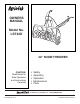
™ OWNERS MANUAL Model No. LST42D 42" SNOW THROWER CAUTION: Read Rules for Safe Operation and Instructions Carefully • • • • • Safety Assembly Operation Maintenance Parts the fastest way to purchase parts www.speedepart.com PRINTED IN U.S.A. FORM NO.
TABLE OF CONTENTS ACCESSORIES..................................................................................................................................................................... 2 SAFETY RULES.................................................................................................................................................................... 3 FULL SIZE HARDWARE CHART................................................................................................................
SAFETY Read and understand the operating instructions before using. Keep the area of operation clear of all persons, especially small children and pets. Thoroughly inspect the area to be cleared and remove all door mats, sleds, boards, wires and other foreign objects. Use extreme caution when operating on or crossing gravel surfaces. Never direct discharge at bystanders or allow anyone in front of the snow thrower. 184045 199682 199683 Do not place hands near rotating parts.
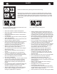
HARDWARE PACKAGE CONTENTS SHOWN ACTUAL SIZE C B A E D 43182 F G 47630 43661 43350 47631 43084 I H J K L 43080 48106 44326 43682 Q V P O 47598 W 44215 46938 43003 N 46584 43088 X 43081 R S,T U M 47572 Y 47810 49933 710-0890A Z 44695 47605, 43070 43082 R19172410 NOT SHOWN ACTUAL SIZE AA CC BB 731-0851A 46959 DD 711-0198 GG FF EE HH II 47134 43343 1643-60 43055 43038 JJ NN LL KK MM 726-0178 23727 46963 25780 47788 48883 4
REF. QTY.
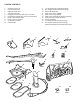
CARTON CONTENTS 1. 2. 3. 4. 5. 6. 7. 8. 9. 10. 11. 12. 13. 14. 15 16. 17. 18. 19. 20. Suspension Arms (2) Left Hand Side Plate Right Hand Side Plate Anti-rotation Bracket Engagement Rod (Not used on some models) Engine Pulley Keeper (Not used on some models) Chute Crank Rod Assembly Support Tube, Crank Rod Lift Handle and Cable Cable Bracket L.H. Hanger Bracket (Outside Mounting) R.H.
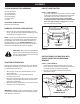
ASSEMBLY TOOLS REQUIRED FOR ASSEMBLY IDENTIFY YOU TRACTOR (2) 7/16" Wrenches (2) 1/2" Wrenches (2) 9/16" Wrenches (2) 3/4" Wrenches (1) Screw Driver (1) Knife STEP 1: (SEE FIGURE 1) • Look under the front of your tractor. If there is a single mower deck suspension bracket located underneath the middle of the front axle, continue on to step 2.
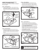
INSTALL SIDE PLATES INSTALL HANGER BRACKETS AND SHOULDER BOLTS TO OUTSIDE OF FRAME STEP 3: (SEE FIGURE 3) • Fasten the R.H. Side Plate (bend facing out) to the front three holes in the tractor frame using three 3/8" x 1" carriage bolts (G), three 1/2" washers (R) (see note) and three 3/8" flange nuts (X). For the rear hole, use a 5/16" x 1" carriage bolt (J), a 1/2" washer (R) and a 5/16" nylock nut (Y). Place the 1/2" washers (R) between the tractor frame and the side plate. Repeat for L.H. side plate.
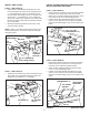
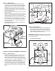
THIS SECTION IS FOR TRACTORS WITH A MANUAL ATTACHMENT CLUTCH STEP 9: (SEE FIGURE 9) • Attach the cable bracket to the slot shown in the clutch/idler assembly using a 5/16" x 3/4" carriage bolt (K) and a 5/16" nylock nut (Y). Place the bolt in the front hole of the bracket and in the end of the slot closest to the pulley. Do not tighten yet. If your tractor has an electric attachment clutch go to step 14 on page 11.
STEP 11: (SEE FIGURE 11) • Find the cable clip that is attached to the left side of the tractor frame underneath the footrest. Open the clip and remove the mower clutch cable. Do not remove the clip from the tractor frame. The cable reattaches to the clip when using the mower deck. • Move the attachment clutch lever on the dash panel to the disengaged position. • Place the clutch/idler assembly on the floor on the left side of the tractor.
THIS SECTION IS FOR TRACTORS WITH AN ELECTRIC ATTACHMENT CLUTCH STEP 16: (SEE FIGURE 16) • Hook one end of the spring supplied in the parts bag through the end link of the tensioning chain. • With the clutch/idler assembly turned upside down, hook the other end of the spring onto the end of the bolt and nut which secure the idler pulley to the upper idler arm. Assemble a 3/8" hex lock nut (Z) onto the bolt and nut, leaving enough gap between the nuts for the spring to pivot freely.
STEP 18: (SEE FIGURE 17) • Turn the clutch/idler assembly right side up. • Slightly loosen the hex bolt next to the flat idler pulley. Install the drive belt down between the hex bolt and the flat idler pulley with the flat side of the belt against the pulley. Retighten the hex bolt. • Loop the belt around the large v-pulley, placing it between the v-pulley and the hex bolt next to the pulley.
INSTRUCTIONS FOR TRACTORS WITH DUAL FRONT DECK SUSPENSION BRACKETS STEP 23: (SEE FIGURE 22) • Remove any bolts found in the holes shown. REMOVE BOLTS IF PRESENT FASTEN SIDE PLATES TO TRACTOR If your tractor resembles figure 20, start with step 21. If your tractor resembles figure 22, start with step 23. STEP 21: (SEE FIGURE 20) • Remove bolts from front three holes shown. • If a bolt is present in the fourth hole, replace it with a 5/16" x 1" carriage bolt (J) without a nut.
INSTALLING SHOULDER BOLTS INSTALLING HANGER BRACKETS For better clearance, lower the tractor's suspension arms using the attachment lift lever. STEP 27: (SEE FIGURE 27) • Remove the bolt, washer and nut which fasten the sway bar bracket to the L.H. side of the tractor frame. Replace with a shoulder bolt (L) and a 3/8" flanged nut (X). Bolt goes on inside of frame. STEP 26: (SEE FIGURE 25 or 26) On Tractors With Foot Rest Brackets • Remove the bolt and nut that fasten the L.H. and R.H.
INSTALLING CLUTCH/IDLER ASSEMBLY This section covers the installation of the Clutch/Idler assembly to tractors with attachment clutches that are either rod operated (p. 15), cable operated (p. 17) or electric (p. 19). Use the appropriate instructions for your tractor. ROD OPERATED MANUAL ATTACHMENT CLUTCH 5/16" NYLOCK NUT (Y) STEP 29: (SEE FIGURE 29) • Move the attachment clutch lever on the dash panel to the disengaged (down) position.
STEP 32: (SEE FIGURE 32) • Be sure to lift up the front end of the engagement rod as shown when performing the next operation. You can temporarily support the rod using a rubber band tied to the engine pulley keeper. • Attach the clutch/idler assembly to the tractor frame as follows. Hook the assembly's notched arms onto the two shoulder bolts you assembled to the inside of the tractor frame. Lift the front of the assembly and attach it to the R.H. and L.H.
CABLE OPERATED MANUAL ATTACHMENT CLUTCH • STEP 35: (SEE FIGURE 35) • Attach the two suspension arms to the rear of the clutch/idler assembly using two 5/16" x 3/4" hex bolts (C), 5/16" washer (Q) and 5/16" nylock nuts (Y) for each arm. Place the arms on the outside of the frame with the notches to the rear. • Insert a tensioning chain through the hole shown and attach the end link to the spring on the lower idler arm. • Slightly loosen the hex bolt next to the flat idler pulley.
STEP 39: (SEE FIGURE 39) • Remove the engine pulley keeper from the side of the tractor frame by removing the washer and nut that secure the keeper. Attach the new pulley keeper supplied with the snow thrower, reusing the original bolt, washer and nut. STEP 40: (SEE FIGURE 40) • Assemble the short "V" belt onto the engine pulley and then onto the large pulley on top of the clutch/idler assembly.
ELECTRIC ATTACHMENT CLUTCHES STEP 43: (SEE FIGURE 43) • Hook the spring from the parts bag through the end of the tensioning chain. • Hook the other end of the spring onto the bottom of the bolt and nut which secure the idler pulley to the upper idler arm. Hold the bolt head and assemble a 3/8" hex lock nut (Z) onto the bolt, leaving enough space for the spring to pivot freely between the two nuts. • Attach a 3/32" hairpin cotter (FF) to the chain, placing it in the fifth link from the spring.
STEP 45: (SEE FIGURE 44) • Turn the clutch/idler assembly right side up. • Slightly loosen the hex bolt next to the flat idler pulley. Install the drive belt down between the hex bolt and the flat idler pulley with the flat side of the belt against the pulley. Retighten the hex bolt. • Loop the belt around the large v-pulley, placing it between the v-pulley and the hex bolt next to the pulley. Place the belt to the inside of the other flat idler pulley.
ASSEMBLY OF THE SNOW THROWER STEP 50: (SEE FIGURE 49) • Tilt the snow thrower back down to the ground. • Remove the nylon tie which fastens the auger drive belt to the discharge housing, leaving the belt assembled around the pulleys. • Remove the nylon tie which fastens the chute crank rod to the crank rod support tube. • Assemble the crank rod support tube to the bracket on the left side of the discharge housing using two 5/16" x 1-1/4" carriage bolts (I), and 5/16" Nylock nuts (Y).
STEP 52: (SEE FIGURE 51) • Attach the chute crank rod assembly brackets to the plastic bracket on the left side of the discharge housing. Align the chute crank bracket beneath the rod support bracket and assemble both to the plastic bracket using two 5/16" x 1" carriage bolts (J), 5/16" washers (Q) and 5/16" Nylock nuts (Y). Do not tighten yet. CHUTE CRANK BRACKET STEP 53: (SEE FIGURE 52) • Coat the top of the ring around the discharge opening with general purpose grease.
ATTACHING SNOW THROWER TO TRACTOR INSTALLING THE AUGER BELT STEP 57: (SEE FIGURE 56) • Remove the attachment pin, if installed. • Push the lift handle down to increase slack in the belt. • Swing the lower idler arm over to the left side. • Place the auger belt around the rear pulley and between the two pulleys on the idler arm. The "V" side of the belt must be seated in the grooves of the V-pulleys. STEP 55: (SEE FIGURE 54) • Place the snow thrower on a flat, level surface.
INSTALLING THE ATTACHMENT PIN ATTACH REFLECTORS TO REAR FENDER STEP 59: (SEE FIGURE 58) • If your tractor is not equipped with rear reflectors, assemble the supplied rear reflectors (KK) to the rear fender. Place the reflectors as close to the bottom of the fender and as far apart as the shape of the fender will allow. STEP 58: (REFER BACK TO FIGURE 54 ON PAGE 23) • Lift the front of the snow blower to align the holes in the mounting plates and the side plates.
OPERATION KNOW YOUR SNOW THROWER Read this owner's manual and safety rules before operating your snow thrower. Compare the illustration below with your snow thrower to familiarize yourself with the various controls and their locations. LIFT RELEASE TRIGGER LIFT HANDLE CHUTE TILT HANDLE CRANK ROD UPPER CHUTE LOWER CHUTE SKID SHOE SCRAPER PLATE SPIRAL AUGERS, R.H. & L.H. CHUTE TILT HANDLE Pivots the Upper Chute up or down to control the angle and distance of discharge.
• RAISING AND LOWERING • To raise, push down on the lift handle until the snow thrower locks in the raised transport position. • To lower, push down slightly on the lift handle and pull the trigger. With the trigger pulled, slowly lower the snow thrower until it reaches the ground. CAUTION: Do not operate the snow thrower without the rear weight attached to the tractor to provide extra traction and stability.
SERVICE AND ADJUSTMENTS LIFT RELEASE CABLE ADJUSTMENT CAUTION: Before servicing or adjusting the snow thrower, shut off the engine, remove the spark plug wire(s), set the parking brake and remove the key from the tractor ignition. • • REPLACING AUGER BELT • • • • • • • • Disengage the tractor's attachment clutch. Lower the snow thrower to the ground. Remove the attachment pin. Lock the snow thrower's lift handle in the down position to decrease belt tension.
STORAGE PARTS TO REMOVE AT END OF SEASON STORAGE RECOMMENDATIONS • • • • • Lower the snow thrower to the ground. Remove the snow thrower from the tractor. Clean the snow thrower thoroughly. Wash off any salt deposit which may have dried on the thrower and housing. Any bare metal that has become exposed should be painted or coated with a light oil to prevent rust. Store in a dry place. • • • • REMOVING THE SPIRAL AUGER HOUSING • • • • • • Lower the snow thrower to the ground. Remove the attachment pin.
NOTES 29
PARTS REPAIR PARTS FOR MODEL LST42D 42" SNOW THROWER 30
REPAIR PARTS FOR MODEL LST42D 42" SNOW THROWER REF. NO. PART NO. 1 2 3 4 5 6 7 8 9 10 11 12 13 14 15 16 17 18 19 20 21 22 23 24 25 26 27 28 29 30 31 32 33 34 35 36 37 38 05931 65701 71464 63579 63768 24773 25982 703-2735A 24816 705-5226 705-5269 705-5270 43840 44950 44917 44326 43080 46703 710-0890A 43088 43070 47189 47810 715-0114 750-0437 731-1379A 43086 43009 711-0469 43081 47615 741-0309 741-0475 741-0493A 24279 48015 784-5618 24393 QTY.
REPAIR PARTS FOR MODEL LST42D 42" SNOW THROWER 62 33 58 11 62 32 63 58 65 65 58 57 61 60 36 32 67
REPAIR PARTS FOR MODEL LST42D 42" SNOW THROWER REF. PART QTY. DESCRIPTION NO. NO. 1 64637 1 Lift Shaft Assembly 2 710-0865 2 Hex Bolt, 1/2-13 x 1" 3 710-0367 2 Hex Bolt, 5/8-11 x 1-1/2" 4 711-0332 2 Pin, Bracket Lift 5 712-0261 2 Nut, Hex Lock 5/8-11 Thread 6 43262 6 Nut, Hex Lock 1/2-13 8 142 5 Pin, Cotter 1/8" x 3/4" 9 43093 1 Pin, Cotter 1/8" x 1-1/2" 10 R19171616 4 Washer, 17/32" x 1" 11 43350 6 Carriage Bolt, 3/8-16 x 1" 12 741-0192 2 Bearing, Flange With Flats 13 783-0380 2 Link, 15.
REPAIR PARTS FOR MODEL LST42D 42" SNOW THROWER 34 REF. NO. PART NO.
SLOPE GUIDE (Keep this sheet in a safe place for future reference.) Use this guide to determine if a slope is safe for the operation of your tractor and snow thrower. Refer also to the instructions in your vehicle owners manual. SIGHT AND HOLD THIS LEVEL WITH A VERTICAL TREE A POWER POLE A CORNER OF A BUILDING OR A FENCE POST FOLD A L O NG DO TTED L INE , R E P RESEN TING A 1 0 D E G REE S LOPE CAUTION: DO NOT OPERATE YOUR TRACTOR AND SNOW THROWER ON A SLOPE IN EXCESS OF 10 DEGREES.
the fastest way to purchase parts www.speedepart.com REPAIR PARTS Agri-Fab, Inc. 809 South Hamilton Sullivan, IL. 61951 217-728-8388 www.agri-fab.com This document (or manual) is protected under the U.S. Copyright Laws and the copyright laws of foreign countries, pursuant to the Universal Copyright Convention and the Berne convention.