
Instructions / Assembly

22
5/16" NYLOCK NUT
CHUTE CRANK
BRACKET
5/16" WASHER
CHUTE
CRANK
ROD
ROD
SUPPORT
BRACKET
5/16" x 1"
CARRIAGE BOLT
SPIRAL
FIGURE 52 LEFT SIDE VIEW
FIGURE 53 RIGHT SIDE VIEW
CHUTE KEEPER
CHUTE SPACER
ANTI-ROTATION
BRACKET
1/4" FLANGED
LOCK NUT
1/4" FLAT
WASHER
1/4" x 1"
HEX BOLT
GREASED
SURFACE
FLANGE
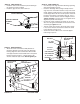
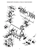
STEP 54: (SEE FIGURE 53)
• Coatthetopoftheringaroundthedischargeopening
with general purpose grease.
• Placethedischargechute(facingforward)ontothe
ring.Placetheanti-rotationbracketontopofthechute
ange,aligningitwiththeholesontherighthandside
oftheange.Attachthethreechutespacersandchute
keeperstothebottomoftheangeusingsix1/4"x1"
hexbolts,1/4"atwashersand1/4"angedlocknuts.
Tighten carefullysothatthenutsaresnugbutdonot
digintotheplasticchutekeepers.
• Positionthecrankrodspiral(seegure51)sothatit
doesnotrubagainstthebottomsofthenotchesinthe
chuteange.Tighten the nuts.
• Turnthecrankrodtocheckifthechuterotatesfreely.
Ifnot,loosentheboltsandnutsthatattachthechute
totheangeby1/4turneach.
• Securethecontrolcablestothecrankrodsupport
tubeusinganylontie.
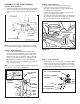
STEP 53: (SEE FIGURE 52)
• Attachthechutecrankrodassemblybracketsto
theplasticbracketontheleftsideofthedischarge
housing.Alignthechutecrankbracketbeneaththe
rodsupportbracketandassemblebothtotheplastic
bracketusingtwo5/16"x1"carriagebolts,5/16"
washersand5/16"Nylocknuts.Do not tighten yet.
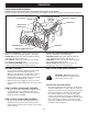
CHUTE CRANK ROD
CHUTE TILT CONTROL
ASSEMBLY
GRIP
FIGURE 51 RIGHT SIDE VIEW
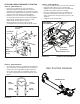
STEP 52: (SEE FIGURE 51)
• Installthechutecrankrodintotheplasticbushingin
thechutetiltcontrolassembly.
• Installthegripontothechutecrankrod.