
Instructions / Assembly

15
INSTALLING CLUTCH/IDLER ASSEMBLY
This section covers the installation of the Clutch/Idler
assemblytotractorswithattachmentclutchesthatare
eitherrodoperated(p.15),cableoperated(p.17)or
electric (p. 19). Use the appropriate instructions for your
tractor.
ROD OPERATED MANUAL ATTACHMENT CLUTCH
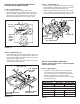
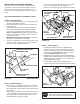
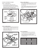
STEP 29: (SEE FIGURE 29)
• Movetheattachmentclutchleveronthedashpanelto
the disengaged (down) position.
• Screwthetrunnionontotheendofthesnowthrower
engagementrod.
• Locatetheclutcharm(wherethemowerclutchrod
was connected) underneath the right hand side the
tractor,justtotheinsideofthesuspensionarm.If
there is an extension attached to the clutch lever, the
extension,boltandnutmustberemovedandstored
withthemowerdeck.
IMPORTANT: Re-attach the extension to the clutch
leverbeforereinstallingthemowerdeck.
• Positiontheengagementrodtotheinsideoftheclutch
armandinsertthedrilledendoftherodthroughthe
arm.Securewitha5/64"hairpincotter.
FIGURE 29 RIGHT SIDE VIEW
ENGAGEMENT ROD
5/64" HAIRPIN
COTTER
TRACTOR'S CLUTCH ARM
SUSPENSION ARM
TRUNNION
REMOVE EXTENSION,
BOLT AND NUT
(IF PRESENT)
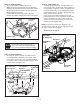
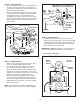
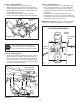
STEP 30: (SEE FIGURE 30)
• Attachthetworearpulleyframebracketstotheinside
oftheclutch/idlerassemblyusingtwo5/16"x1"hex
bolts,eight5/16"washersandtwo5/16"nylocknutsfor
eachbracket.
• Attachthetwofrontpulleyframebracketstotheinside
oftheclutch/idlerassemblyusingtwo5/16"x3/4"hex
bolts,5/16"washersand5/16"nylocknutsforeach
bracket.Addextrawashersifneeded.
FIGURE 30
FIGURE 31
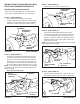
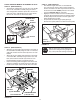
STOP
Didyouchoosethecorrectdrivebeltfor
yourtractor?Usingthewronglengthbelt
maycauseprematurebearingorbeltfailure.
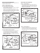
STEP 31: (SEE FIGURE 31)
• Twodifferentlengthdrivebeltsareincludedwith
yoursnowthrower.Tractorswithmanualattachment
clutchesanddualfrontdecksuspensionbracketsuse
the55"drivebeltwith#46989 printed on the outside
ofthebelt.DO NOT USEtheotherbelt.
• Slightlyloosenthehexboltnexttotheatidlerpulley.
Installthedrivebeltdownbetweenthehexboltandthe
atidlerpulleywiththeatsideofthebeltagainstthe
pulley.Retightenthehexbolt.
• Loopthebeltaroundthelargev-pulley,placingit
betweenthev-pulleyandthehexboltnexttothepulley.
TENSIONING CHAIN
(lower idler arm)
5/16" x 3/4"
HEX BOLT
5/16" x 1"
HEX BOLT
5/16" NYLOCK NUT
5/16"
WASHER
(4) 5/16" WASHERS
3/32" HAIRPIN
COTTER IN
4th LINK
#46989
DRIVE BELT
FLAT IDLER
PULLEY
HEX BOLTS
• Insertatensioningchainthroughtheholeshownand
attachittothespringontheloweridlerarm.
• Installa3/32"hairpincotterinthe4thlinkofthechain.