
Instructions / Assembly

14
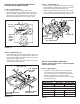
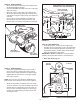
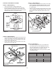
FIGURE 28 RIGHT SIDE VIEW
INSTALLING HANGER BRACKETS
Forbetterclearance,lowerthetractor'ssuspensionarms
usingtheattachmentliftlever.
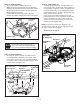
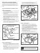
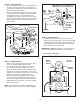
STEP 26: (SEE FIGURE 25 or 26)
On Tractors With Foot Rest Brackets
• RemovetheboltandnutthatfastentheL.H.andR.H.
footrestbracketstotheframe.
• AttachtheL.H.HangerBracket(marked"L")tothe
insideofthetractorframeusingtwo3/8"x1"carriage
boltsand3/8"angednuts.Boltheadsgooninsideof
tractorframe.RepeatfortheR.H.side.
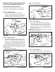
FIGURE 26 LEFT SIDE VIEW
FIGURE 25 LEFT SIDE VIEW
On Tractors Without Foot Rest Brackets
• Findtheemptyholebeneaththefootrest.Attachthe
L.H.HangerBracket(marked"L")totheinsideof
theframeusinga3/8"x1"carriageboltanda3/8"
angednut.Boltheadgoesoninsideoftractorframe.
Repeat for the R.H. side.
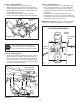
STEP 28: (SEE FIGURE 28)
• Assembleashoulderboltand3/8"angednuttothe
R.H.sideofthetractorframe,usingtherstempty
holetotherearoftheR.H.hangerbracket.Boltgoes
oninsideofframe.
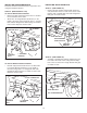
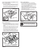
FIGURE 27 LEFT SIDE VIEW
INSTALLING SHOULDER BOLTS
STEP 27: (SEE FIGURE 27)
• Removethebolt,washerandnutwhichfastenthe
swaybarbrackettotheL.H.sideofthetractorframe.
Replacewithashoulderboltanda3/8"angednut.
Boltgoesoninsideofframe.
BOLT REMOVED
FROM THIS HOLE
SWAY BAR
BRACKET
SHOULDER BOLT
3/8"
FLANGED
NUT
3/8" x 1"
CARRIAGE
BOLT
3/8" FLANGED NUT
L.H. HANGER
BRACKET
SUSPENSION ARM
SHOULDER BOLT
3/8"
FLANGED
NUT
R.H. HANGER BRACKET
BOLT REMOVED
FROM THIS HOLE
3/8" x 1"
CARRIAGE
BOLT
3/8" FLANGED
NUT
L.H. HANGER
BRACKET
SUSPENSION ARM