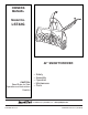
OWNERS MANUAL Model No. LST42G 42" SNOW THROWER CAUTION: Read Rules for Safe Operation and Instructions Carefully • • • • • Safety Assembly Operation Maintenance Parts the fastest way to purchase parts www.speedepart.com PRINTED IN U.S.A. FORM NO. 28156 rev.
TABLE OF CONTENTS SAFETY RULES.................................................................................................................................................................... 3 FULL SIZE HARDWARE CHART.......................................................................................................................................... 4 CARTON CONTENTS.......................................................................................................................................
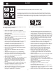
SAFETY Read and understand the operating instructions before using. Keep the area of operation clear of all persons, especially small children and pets. Thoroughly inspect the area to be cleared and remove all door mats, sleds, boards, wires and other foreign objects. Use extreme caution when operating on or crossing gravel surfaces. Never direct discharge at bystanders or allow anyone in front of the snow thrower. 184045 199682 199683 Do not place hands near rotating parts.
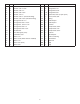
HARDWARE PACKAGE CONTENTS SHOWN ACTUAL SIZE D C B A F E G 43182 43084 47630 43661 43063 47631 J I K L M 43080 48106 44326 H 43682 Q O 43350 46938 V P 47598 44215 W 43003 46584 43088 R X 43081 S,T U N 47572 Y 47810 Z 44695 47605, 43070 43082 R19172410 42849 NOT SHOWN ACTUAL SIZE AA 46959 27809 27810 EE HA3090 HH II 43343 43055 23727 43038 KK JJ 46963 42848 GG FF DD CC BB LL 47788 726-0178 4 MM HA9822 NN 42991
REF. QTY. DESCRIPTION REF. QTY.
CARTON CONTENTS 1. 2. 3. 4. 5. 6. 7. 8. 9. 10. 11. 12. Housing Assembly Lift Handle and Cable Crank Rod Support Tube Chute Crank Rod Assembly Engagement Rod (Not used on some models) Cable Bracket Engine Pulley Keeper (Not used on some models) Chute and Control Cable Assembly Clutch Idler Assembly Rear Pulley Frame Bracket (2) Anti-rotation Bracket. Front Pulley Frame Bracket (2) 13. 14. 15. 16. 17. 18. 19. 20. 21. 22. 23.
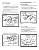
ASSEMBLY TOOLS REQUIRED FOR ASSEMBLY IDENTIFY YOU TRACTOR (2) 7/16" Wrenches (2) 1/2" Wrenches (2) 9/16" Wrenches (2) 3/4" Wrenches (1) Knife STEP 1: (SEE FIGURE 1) • Look under the front of your tractor. If there is a single mower deck suspension bracket located underneath the middle of the front axle, continue on to step 2. If your tractor does not have a mower deck suspension bracket underneath the middle of the front axle, skip to step 21 on page 13 for tractors with dual suspension brackets.
INSTALL SIDE PLATES INSTALL HANGER BRACKETS AND SHOULDER BOLTS TO OUTSIDE OF FRAME STEP 3: (SEE FIGURE 3) • Fasten the R.H. Side Plate (bend facing out) to the front three holes in the tractor frame using three 3/8" x 1" carriage bolts, three 1/2" washers (see note) and three 3/8" flange nuts. For the rear hole, use a 5/16" x 1" carriage bolt, a 1/2" washer and a 5/16" nylock nut. Place the 1/2" washers between the tractor frame and the side plate. Repeat for L.H. side plate.
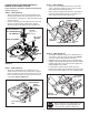
THIS SECTION IS FOR TRACTORS WITH A MANUAL ATTACHMENT CLUTCH STEP 9: (SEE FIGURE 9) • Attach each rear pulley frame bracket to the inside of the clutch frame using two 5/16" x 3/4" hex bolts, 5/16" washers and 5/16" nylock nuts. • Attach each front pulley frame bracket to the inside of the clutch frame using two 5/16" x 1" hex bolts, four 5/16" washers and two 5/16" nylock nuts. If your tractor has an electric attachment clutch go to step 14 on page 11.
STEP 11: (SEE FIGURE 11) • Find the cable clip that is attached to the left side of the tractor frame underneath the footrest. Open the clip and remove the mower clutch cable. Do not remove the clip from the tractor frame. The cable reattaches to the clip when using the mower deck. • Move the attachment clutch lever on the dash panel to the disengaged position. • Place the clutch/idler assembly on the floor on the left side of the tractor.
THIS SECTION IS FOR TRACTORS WITH AN ELECTRIC ATTACHMENT CLUTCH STEP 16: (SEE FIGURE 16) • Attach each rear pulley frame bracket to the inside of the clutch/idler assembly using two 5/16" x 3/4" hex bolts, 5/16" washers and 5/16" nylock nuts. • Attach each front pulley frame bracket to the inside of the clutch/idler assembly using two 5/16" x 1" hex bolts, four 5/16" washers and two 5/16" nylock nuts. STEP 14: (SEE FIGURE 14) • Turn the clutch idler assembly upside down.
STEP 18: (SEE FIGURE 17) • Turn the clutch/idler assembly right side up. • Slightly loosen the hex bolt next to the flat idler pulley. Install the drive belt down between the hex bolt and the flat idler pulley with the flat side of the belt against the pulley. Retighten the hex bolt. • Loop the belt around the large v-pulley, placing it between the v-pulley and the hex bolt next to the pulley. HEX BOLTS STEP 20: (SEE FIGURE 19) • Assemble the drive belt onto the engine pulley.
INSTRUCTIONS FOR TRACTORS WITH DUAL FRONT DECK SUSPENSION BRACKETS STEP 23: (SEE FIGURE 22) • Remove any bolts found in the holes shown. REMOVE BOLTS IF PRESENT FASTEN SIDE PLATES TO TRACTOR If your tractor resembles figure 20, start with step 21. If your tractor resembles figure 22, start with step 23. STEP 21: (SEE FIGURE 20) • Remove bolts from front three holes shown. • If a bolt is present in the fourth hole, replace it with a 5/16" x 1" carriage bolt without a nut.
INSTALLING SHOULDER BOLTS INSTALLING HANGER BRACKETS For better clearance, lower the tractor's suspension arms using the attachment lift lever. STEP 27: (SEE FIGURE 27) • Remove the bolt, washer and nut which fasten the sway bar bracket to the L.H. side of the tractor frame. Replace with a shoulder bolt and a 3/8" flanged nut. Bolt goes on inside of frame. STEP 26: (SEE FIGURE 25 or 26) On Tractors With Foot Rest Brackets • Remove the bolt and nut that fasten the L.H. and R.H.
• INSTALLING CLUTCH/IDLER ASSEMBLY This section covers the installation of the Clutch/Idler assembly to tractors with attachment clutches that are either rod operated (p. 15), cable operated (p. 17) or electric (p. 19). Use the appropriate instructions for your tractor. • Insert a tensioning chain through the hole shown and attach it to the spring on the lower idler arm. Install a 3/32" hairpin cotter in the 4th link of the chain.
STEP 32: (SEE FIGURE 32) • Be sure to lift up the front end of the engagement rod as shown when performing the next operation. You can temporarily support the rod using a rubber band tied to the engine pulley keeper. • Attach the clutch/idler assembly to the tractor frame as follows. Hook the assembly's notched rear pulley frame brackets onto the two shoulder bolts you assembled to the inside of the tractor frame. Lift the front of the assembly and attach it to the R.H. and L.H.
CABLE OPERATED MANUAL ATTACHMENT CLUTCH STEP 37: (SEE FIGURE 37) • Two different length drive belts are included with your snow thrower. Tractors with manual attachment clutches and dual front deck suspension brackets use the 55" drive belt with #46989 printed on the outside of the belt. DO NOT USE the other belt. • Slightly loosen the hex bolt next to the flat idler pulley. Install the drive belt down between the hex bolt and the flat idler pulley with the flat side of the belt against the pulley.
STEP 38: (SEE FIGURE 38) • Move the attachment clutch lever on the dash panel to the disengaged (down) position. • Place the clutch/idler assembly on the floor on the right side of the tractor. • Attach the tractor's clutch cable to the cable bracket. Secure the cable housing guide (groove down) to the cable bracket using the original collar and a 5/64" hair cotter pin. • Place a spacer on the welded pin on the idler arm.
ELECTRIC ATTACHMENT CLUTCHES STEP 43: (SEE FIGURE 43) • Attach the two rear pulley frame brackets to the inside of the clutch/idler assembly using two 5/16" x 1" hex bolts, eight 5/16" washers and two 5/16" nylock nuts for each bracket. • Attach the two front pulley frame brackets to the inside of the clutch/idler assembly using two 5/16" x 3/4" hex bolts, 5/16" washers and 5/16" nylock nuts for each bracket. STEP 41: (SEE FIGURE 41) • Turn the clutch idler assembly upside down.
STEP 45: (SEE FIGURE 44) • Turn the clutch/idler assembly right side up. • Slightly loosen the hex bolt next to the flat idler pulley. Install the drive belt down between the hex bolt and the flat idler pulley with the flat side of the belt against the pulley. Retighten the hex bolt. • Loop the belt around the large v-pulley, placing it between the v-pulley and the hex bolt next to the pulley.
ASSEMBLY OF THE SNOW THROWER STEP 50: (SEE FIGURE 49) • Tilt the snow thrower back down to the ground. • Remove the nylon tie which fastens the auger drive belt to the discharge housing, leaving the belt assembled around the pulleys. • Remove the nylon tie which fastens the chute crank rod to the crank rod support tube. • Assemble the crank rod support tube to the bracket on the left side of the discharge housing using two 5/16" x 1-1/4" carriage bolts, and 5/16" Nylock nuts.
STEP 52: (SEE FIGURE 51) • Install the chute crank rod into the plastic bushing in the chute tilt control assembly. • Install the grip onto the chute crank rod. STEP 54: (SEE FIGURE 53) • Coat the top of the ring around the discharge opening with general purpose grease. • Place the discharge chute (facing forward) onto the ring. Place the anti-rotation bracket on top of the chute flange, aligning it with the holes on the right hand side of the flange.
ATTACHING SNOW THROWER TO TRACTOR STEP 57: (SEE FIGURE 56) • Push the lift handle down to increase slack in the belt. • Swing the lower idler arm over to the left side. • Slightly loosen the belt keeper bolts located beside the idler arm V-pulley and the rear V-pulley. • Place the auger belt around the rear V-pulley and between the two pulleys on the idler arm. The "V" side of the belt must be seated in the grooves of the V-pulleys. • Retighten the two keeper bolts.
SETTING THE AUGER BELT TENSION ATTACH REFLECTORS TO REAR FENDER STEP 60: (SEE FIGURE 59) • If your tractor is not equipped with rear reflectors, assemble the supplied rear reflectors to the rear fender. Place the reflectors as close to the bottom of the fender and as far apart as the shape of the fender will allow. STEP 58: (SEE FIGURE 57) • Pull the tensioning chain until it is extended out as far as the 3/32" hairpin cotter installed in the chain will allow.
OPERATION KNOW YOUR SNOW THROWER Read this owner's manual and safety rules before operating your snow thrower. Compare the illustration below with your snow thrower to familiarize yourself with the various controls and their locations. LIFT RELEASE TRIGGER LIFT HANDLE CHUTE TILT HANDLE CRANK ROD UPPER CHUTE LOWER CHUTE SKID SHOE SCRAPER PLATE SPIRAL AUGERS, R.H. & L.H. CHUTE TILT HANDLE Pivots the Upper Chute up or down to control the angle and distance of discharge.
• RAISING AND LOWERING • To raise, push down on the lift handle until the snow thrower locks in the raised transport position. • To lower, push down slightly on the lift handle and pull the trigger. With the trigger pulled, slowly lower the snow thrower until it reaches the ground. CAUTION: Do not operate the snow thrower without the rear weight attached to the tractor to provide extra traction and stability.
SERVICE AND ADJUSTMENTS LIFT RELEASE CABLE ADJUSTMENT CAUTION: Before servicing or adjusting the snow thrower, shut off the engine, remove the spark plug wire(s), set the parking brake and remove the key from the tractor ignition. • • REPLACING AUGER BELT • • • • • • • • Disengage the tractor's attachment clutch. Lower the snow thrower to the ground. Remove the clevis pins. See figure 54 on page 23. Lock the snow thrower's lift handle in the down position to decrease belt tension.
ADJUSTING LIFT HEIGHT, LEVELING The snow thrower is equipped with two threaded lift links for adjusting the lift height and leveling of the snow thrower in the raised position. TO ADJUST THE LIFT HEIGHT: • Raise the snow thrower to the highest position. • Check the clearance between the rear of the idler bracket (item 39, page 30) and the lift shaft assembly (item 1, page 32). A minimum 1/16" clearance in the raised position is necessary to avoid possible damage to the lift system.
TROUBLESHOOTING PROBLEM CAUSE CORRECTION Spiral augers don't turn 1. Upper or lower V belt too loose 2. Upper or lower V belt broken 3. Shear bolts are sheared. 1. Increase tension on V belt 2. Replace V belt 3. Replace shear bolts Clogged discharge chute 1. Tractor ground speed too fast 2. Tractor throttle set too low 3. Snow too deep 4. Snow melts during contact with the snow thrower 1. Use lower tractor gear 2. Increase to full throttle 3. Raise the snow thrower 4.
REPAIR PARTS FOR MODEL LST42G 42" SNOW THROWER 38 30 45 30 38 33 67 66 60 20 34 68 53 27 12 23 15 22 59 20 23 19 36 23 14 10 14 22 20 36 30 11 64 48 47 62 23 37 27 31 34 63 13 30 35 30 28 17 7 13 19 30 23 30 29 23 17 3 24 16 5 6 2 1 17 23 26 4 55 61 44 8 32 25 23 35 16 9 50 25 49 23 30 54 23 30 18 52 50 56 54 54 40 46 43 42 57 40 8 41 54 39 46 65 21 49 21 65 18 51 40 43 58 18 51
REPAIR PARTS FOR MODEL LST42G 42" SNOW THROWER REF 1 2 3 4 5 6 7 8 9 10 11 12 13 14 15 16 17 18 19 20 21 22 23 24 25 26 27 28 29 30 31 32 33 34 35 PART NO 28237 67629 71464 47026 67632 24773 25982 27508 24816 27510 67689 67688 43063 44950 HA20185 44326 43080 47630 42849 43088 43070 47189 47810 41625 42846 43086 43009 27915 27916 43081 47615 42844 43182 42953 24279 QTY 2 1 1 1 1 1 1 2 1 1 1 1 4 4 1 4 12 8 2 10 2 4 29 2 3 6 6 1 1 22 2 1 1 4 2 DESCRIPTION Flange, Bearing Housing Assembly Gear Assembly Pull
REPAIR PARTS FOR MODEL LST42G 42" SNOW THROWER 44 40 43 41 44 45 42 30 65 53 63 47 44 48 46 51 39 63 28 70 50 66 63 49 53 52 64 59 59 6 2 14 6 13 69 68 10 8 58 97 3 15 58 12 6 1 8 67 8 10 69 68 17 18 16 5 31 62 14 6 54 4 67 33 11 12 58 15 52 13 18 5 32 31 62 55 4 2 18 17 19 27 58 8 63 58 25 25 3 65 65 57 61 60 36 34 56 35 32 59 59 6 29 22 26 23 24 8 21 24 63 20 35 37 38 6
REPAIR PARTS FOR MODEL LST42G 42" SNOW THROWER REF PART NO QTY DESCRIPTION 1 68550 1 Lift Shaft Assembly 2 41616 2 Hex Bolt, 1/2-13 x 1" 3 41614 2 Hex Bolt, 5/8-11 x 1-1/2" 4 42842 2 Pin, Clevis 1/2" x 78" 5 41615 2 Nut, Hex Lock 5/8-11 Thread 6 43262 6 Nut, Hex Lock 1/2-13 7 43601 1 Washer, 1.59" x 1.032" x .
REPAIR PARTS FOR MODEL LST42G 42" SNOW THROWER 42 43 41 23 17 24 31 34 45 11 46 34 47 26 16 19 21 36 20 15 19 41 39 38 32 34 53 50 51 52 51 7 48 8 41 40 37 14 29 25 3 18 54 12 12 12 35 17 34 53 31 10 44 10 17 12 17 5 2, 22 4 1 10 30 10 30 55 25 54 13 27 24 17 23 12 27 28 29 30 31 32 33 34 35 36 37 38 39 40 41 42 43 44 45 46 47 48 49 50 51 52 53 54 55 6 17 12 3 2 49 21 17 12 10 17 21 REF 7 8 9 10 11 12 13 14 15 16 17 18 19 20 21 22 23 24 25 26 35 37 40 36 9 34 33 28
SLOPE GUIDE (Keep this sheet in a safe place for future reference.) Use this guide to determine if a slope is safe for the operation of your tractor and snow thrower. Refer also to the instructions in your vehicle owners manual. SIGHT AND HOLD THIS LEVEL WITH A VERTICAL TREE A POWER POLE A CORNER OF A BUILDING OR A FENCE POST FOLD A L O NG DO TTED L INE , R E P RESEN TING A 1 0 D E G REE S LOPE CAUTION: DO NOT OPERATEYOURTRACTOR AND SNOWTHROWER ON A SLOPE IN EXCESS OF 10 DEGREES.
the fastest way to purchase parts www.speedepart.com REPAIR PARTS Agri-Fab, Inc. 809 South Hamilton Sullivan, IL. 61951 217-728-8388 www.agri-fab.com This document (or manual) is protected under the U.S. Copyright Laws and the copyright laws of foreign countries, pursuant to the Universal Copyright Convention and the Berne convention.