
Use and Care Manual

11
ENGLISH
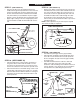
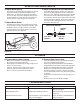
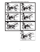
STEP 17: (SEE FIGURE 17)
• Fromtheleftside,inserttheweldedendofthelift
handlerodthroughtheexposedholesintheendofthe
channelassembly.Next,inserttheliftlinkpinthrough
theholeinthebracketthatisweldedtothelifthandle
rod.(Theliftlinkispre-assembledtothepivotsupport
bracket).Securethebracketwithasmallhairpincotter.
• Applyalightcoatingofoiltothestraightupperportion
ofthelifthandlerod.Slidethelifthandletubeontothe
rod.
LIFT HANDLE ROD
HAIRPIN COTTER (N)
LONG PIN
(LIFT LINK)
WELDED BRACKET
LIFT HANDLE TUBE
5/16" x 1"
CARRIAGE BOLT (V)
5/16" x 3/4"
CARRIAGE BOLT (W)
5/16" WASHER (BB)
5/16" NYLOCK NUT (H)
SKID SHOE
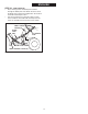
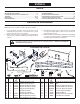
STEP 18: (SEE FIGURE 18)
• Pivotthebladetothecenterpositionandloweritto
theground.Placeshimsunderthebladetocreate
theamountofgroundclearanceyouwant.Themore
uneventhesurfacethemoreclearanceyouwillneed.
• Attachtheskidshoestothebladeusinga5/16"x3/4"
carriageboltinthetopholeanda5/16"x1"carriage
boltinthebottomhole.Withtheskidshoesrestingon
theground,securetheboltswith5/16"washersand
5/16"nylocknuts.
FIGURE 18 (Left Hand Side View)
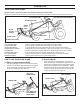
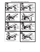
FIGURE 19 (Right Hand Side View)
FIGURE 20 (Right Hand Side View)
CABLE END
FITTING (DD)
STEP 19: (SEE FIGURE 19)
• Removetherubbercapandtherstjamnutfromthe
threadedendofthecontrolcableandslidethemonto
thecontrolcablewire.Adjustthesecondjamnuton
thethreadssothatitisapproximately3/4"fromend.
Assemblethreadedendofcablethroughthecable
mountbracketonthelifthandletubeandsecureit
withtherstjamnut.Reinstalltherubbercapontothe
threadedcableend.
NOTE: Someadjustmentofjamnutsmayberequired
afterbladeassemblyiscompleted.
STEP 20: (SEE FIGURE 20)
• Assembletheplasticgripontothegripassembly.
• Attachthegripassemblytothelifthandletubeusing
one5/16"x1-1/2"hexboltandone5/16"nylocknut.
Donotovertightenthenylocknut.Thegripassembly
mustpivotfreely.
• Assembletheballendofthecabletoacableend
ttingaswasdonetotheotherendofthecable.
Securethecableendttingtotheweldboltonthelock
releasegripwitha1/4"nylocknut.Donotovertighten
thenylocknut.Thecablettingmustpivotfreely.
RUBBER
CAP
CABLE MOUNT BRACKET
JAM NUTS
3/4"
CONTROL CABLE END
5/16" x 1-1/2"
HEX BOLT (D)
PLASTIC
GRIP
1/4" WELD
BOLT
CABLE END
FITTING (DD)
5/16" NYLOCK
NUT (H)
1/4 " NYLOCK
NUT (G)
CABLE
GRIP
ASSEMBLY
FIGURE 17 (Left Hand Side View)