™ owners manual Model No. 45-03431 DETHATCHER FOR SWEEPERS CAUTION: Read Rules for Safe Operation and Instructions Carefully • • • • • Safety Assembly Operation Maintenance Parts the fastest way to purchase parts www.speedepart.com PRINTED IN U.S.A. FORM NO.
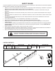
SAFETY RULES Any power equipment can cause injury if operated improperly or if the user does not understand how to operate the equipment. Exercise caution at all times, when using power equipment. • • • • • • • • • • • • Read this owners manual carefully for operating and service instructions before attempting to assemble or operate the dethatcher. Be thoroughly familiar with the proper use of the dethatcher.
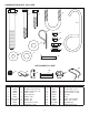
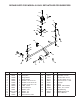
HARDWARE PACKAGE - FULL SIZE 5 6 8 7 9 13 14 15 12 16 17 11 10 18 NOT SHOWN FULL SIZE 24 19 REF. 5 6 7 8 9 10 11 12 13 14 20 22 23 21 part no. qty. description 46526 3 Hex Bolt, 1/2-13 x 3-1/2" 44292 2 Hex Bolt, 5/16-18 x 2-1/2" 43085 7 Hex Bolt, 5/16-18 x 1-1/2" 48813 2 U-Bolt, 1/4-20 48811 1 Hook, Transport 43081 2 Washer, 5/16" R19171616 2 Washer, 1/2" 43070 14 Washer, 3/8" 43055 2 Hair Cotter Pin, 3/32" 47189 4 Nylock Nut, 1/4-20 REF. 15 16 17 18 19 20 21 22 23 24 3 part no.
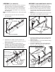
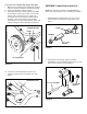
ASSEMBLY (ALL MODELS) ASSEMBLY (NON-SMARTSWEEP MODELS) 1. Assemble seven spring tines to the top of the frame tube. Use a 5/16" x 1-1/2" hex bolt, two 3/8" flat washers and a 5/16" nylock nut for each spring tine. Place one 3/8" flat washer on top of the frame tube and the second 3/8" flat washer on top of the spring tine. See figure 1. NOTE: On sweepers smaller than 42", use only five spring tines. 1.
ASSEMBLY (SMARTSWEEP MODELS) If you have a 30" sweeper, skip steps 7 through 9. 7. Make sure the sweeper height adjustment handle is still set to about the middle of it's adjustment range. 8. Center the dethatcher with the sweeper. 9. Assemble the keeper brackets (bend to the inside) to the sweeper's hitch tube, outside of the conduit clamps. Use a u-bolt and two 1/4" nylock nuts per bracket. Position the keeper brackets against the sides of the conduit clamps, approximately perpendicular to the ground.
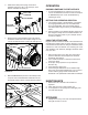
OPERATION 3. Fasten each clamp to the spring mount frame assembly using one 5/16 x 1-3/8" clevis pin, 5/16" washer, and 3/32" hair cotter pin. RAISING/LOWERING THE DETHATCHER 1. To raise the dethatcher for transport, lift up on the front of the dethatcher and secure it with the transport or SMARTSweep hook. Lower the dethatcher by releasing the hook. 5/16 x 1-3/8" CLEVIS PIN 5/16" WASHER SETTING THE OPERATING POSITION 1.
REPAIR PARTS FOR MODEL 45-03431 DETHATCHER FOR SWEEPERS 6 5 4 17 7 15 12 18 10 20 23 22 2 23 12 13 24 19 18 1 15 10 20 17 8 21 14 19 REF. 1 2 3 4 5 6 7 8 9 10 11 12 13 16 11 13 11 3 9 5 part no. qty. description 64650 1 Spring Mount Frame Assem.
the fastest way to purchase parts www.speedepart.com REPAIR PARTS Agri-Fab, Inc. 303 West Raymond Sullivan, IL. 61951 217-728-8388 www.agri-fab.com This document (or manual) is protected under the U.S. Copyright Laws and the copyright laws of foreign countries, pursuant to the Universal Copyright Convention and the Berne convention.