™ owners manual APPLICATIONTIPS xxxxxxxxxxxxxxx xxxxxxxxxxxxxxxxxxxxxx xxxxxxxxxxxxxxxxxxxx xxxxxxxxxxxxxxxxxxxxxx xxxxxxxxxxxxxxxxxxxxx xxxxxxxxxxxxxxxxxxxxxx xxxxxxxxxxxxxxxxxxx xxxxxxxxxxxxxxxxxxxxxx MANUAL DEL USUARIO NOTICE D’UTILISATION xxxxx xxxxx xxxxxxxxxxxxxxxx xxxxx xxxxx xxxxx xxxxxx xxxxxx xxxxxx xxx xxx xxx xxxxxx xxxxx xxxxxx Model No. Modelo No. Modèle No.
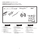
CARTON CONTENTS (Loose Parts in Carton) CONTENIDO DE LA CAJA (Partes Sueltas en la Caja) CONTENU DU CARTON (Pièces en Vrac Dans le Carton) 1 4 2 F F O 5 6 3 7 N O 1 2 3 4 5 6 7 8 9 10 8 ESPAÑOL ENGLISH 1. 2. 3. 4. 5. 6. 7. 8. Hitch Tube Flow Control Arm Hitch Bracket Flow Control Mount Bracket Braces (2) Flow Control Rod Wheels (2) Hopper Assembly Hardware Pack (see page 3) 1. 2. 3. 4. 5. 6. 7. 8.
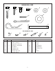
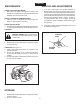
SHOWN FULL SIZE B A E D C F G H I J K NOT SHOWN FULL SIZE L M O N ref. qty. ref. qty.
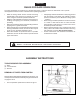
ENGLISH RULES FOR SAFE OPERATION Any power equipment can cause injury if operated improperly or if the user does not understand how to operate the equipment. Exercise caution at all times when operating equipment. • • • • • Read the towing vehicle owners manual and towing vehicle safety rules. Know how to operate your tractor before using the broadcast spreader attachment. Read the chemical label instructions and cautions for handling and applying the chemicals purchased for spreading.
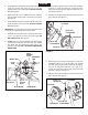
ENGLISH 2. Assemble the two hitch braces to the inside of the hopper frame, one on each side, using two 1/4" x 1-1/2" hex bolts (A) and two 1/4" nylock nuts (D). DO NOT TIGHTEN YET. See figure 2. 7. Select the end of the axle with no cross hole. Assemble a spacer (L), a 5/8" flat washer (G), a wheel (air valve facing out) and then another 5/8" flat washer (G) onto the axle. See figure 3. 3. Remove the nut from the middle bolt in the crossover tube and shaft support plate. Leave the bolt in place.
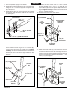
ENGLISH 11. Turn the spreader upright on its wheels. 12. Assemble the hitch bracket to the top of the hitch tube using two 1/4" x 1" hex bolts (B) and 1/4" nylock nuts (D). See figure 5. 13. Assemble the hitch pin (K) through the hitch bracket and the hitch tube and secure with the hair cotter pin (J). See figure 5. 15. Assemble the flow control arm to the flow control mounting bracket using a 1/4" x 1" hex bolt (B), two nylon washers (E) and a 1/4" nylock nut (D) as shown in figure 7. Tighten carefully.
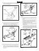
ENGLISH 18. Hook the free end of the flow control rod through the hole in the slide gate bracket located near the bottom of the hopper. See figure 9. (M) NYLON WING NUT F F O (F) 5/16" FLAT WASHER N O 1 (E) NYLON WASHER 2 3 4 5 6 7 8 9 10 (N) ADJUSTABLE STOP (C) 1/4" x 3/4" CARRIAGE BOLT FIGURE 11 21. Position the flow control mounting bracket (figure 12). a. Push on flow control arm until it locks in "OFF" position. b.
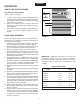
ENGLISH OPERATION HOW TO USE YOUR SPREADER SETTING THE FLOW CONTROL (Refer to figure 12 on page 7.) REFER TO CHARTS 1. Loosen the nylon wing nut, set the adjustable stop to the desired flow rate setting and retighten the wing nut. The higher the setting number, the wider the opening in the bottom of the hopper. 2. Refer to the application chart on page 8 and to the instructions on the fertilizer bag to select the proper flow rate setting. 3.
ENGLISH MAINTENANCE SERVICE AND ADJUSTMENTS 1. If the axle, slotted gear and sprocket assembly is disassembled, mark down the positions of the parts as they are removed.The drive wheel and sprocket positions in relation to the slotted gear determine which direction the spreader plate will spin. Be sure to reassemble them in their original positions. (Refer to figure 4 on page 5.) Use shim washers (Ref. no. 21 on pages 18 and 19) as needed for minimum backlash. Add grease to gear and sprocket.
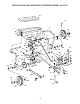
REPAIR PARTS FOR BROADCAST SPREADER MODEL 45-02114 51 13 4 1 38 40 39 31 5 30 A 2 9 7 40 9 9 22 37 29 48 3 15 26 A 27 4 9 37 35 6 B 34 46 9 28 37 9 D 40 9 10 19 36 29 9 24 45 21 43 20 44 39 11 9 8 39 48 11 48 9 21 22 11 9 17 9 35 14 D 30 32 37 33 22 47 22 38 E 22 24 50 42 19 23 18 23 25 B E 16 16 18 11 37 41 49 39 48
REPAIR PARTS FOR BROADCAST SPREADER MODEL 45-02114 REF. PART NO. QTY. DESCRIPTION 1 44466 1 Hopper 2 C-9M5732 2 Rivet, Pop 3 62482 1 Ass'y, Guide Closure 4 48842 1 Tube, Frame 5 23753 1 Slide Gate Angle Bracket 6 23758 1 Slide Gate Bracket 7 44566 1 Spring, Torsion 8 24857 1 Flow Control Link 9 47189 22 Nut, Nylock 1/4-20 10 48841 1 Tube, Crossover 11 R19111116 6 Washer, 5/16 SAE 13 47063 1 Pin, Cotter 5/32" x 2" 14 44586 1 Tube, Hitch 15 46055 1 Pin, Spring 1/8" Dia. x 1" Lg.
the fastest way to purchase parts www.speedepart.com REPAIR PARTS Agri-Fab, Inc. 303 West Raymond Sullivan, IL. 61951 217-728-8388 www.agri-fab.com This document (or manual) is protected under the U.S. Copyright Laws and the copyright laws of foreign countries, pursuant to the Universal Copyright Convention and the Berne convention.