
Use and Care Guide

8
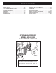
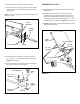
FIGURE 4
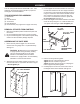
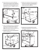
8. To prevent accidental tipping during the following
assembly procedures, lower the cart to rest upside
down, with the wheel support facing up, as shown in
gure5.
9. Align the latch stand bracket so that the tab is at the
rear. Fasten the bracket to the rear set of holes at the
front of the cart using two 1/4" x 5/8" hex bolts, 1/4"
atwashersand1/4"nylocknuts.Usethe1/4"at
washers as shims between the bracket and the cart
bed. Makengertight.Seegure5.
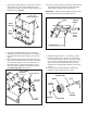
FIGURE 6
FIGURE 7
10. Position the rear tongue on the wheel support and the
latch stand bracket. Assemble the axle through the
wheel support and the tongue. Seegure6.
IMPORTANT: Make sure the tongue is securely locked
to the latch stand bracket by the latch lock lever.
7. Assemble the wheel support to the bottom of the cart
using eight 5/16" x 3/4" truss head bolts and 5/16"
nylocknutsasshowningure4.Headsofboltsgoon
the inside of cart. Tighten.
AXLE
TONGUE
(REAR)
LATCH
LOCK
LEVER
COTTER PIN
WHEEL
HUB CAP
1" FLAT
WASHER
1" FLAT
WASHER
AXLE
SPACER TUBE
FIGURE 5
5/16"
NYLOCK
NUT
WHEEL
SUPPORT
5/16" x 3/4"
TRUSS HEAD BOLT
LATCH STAND
BRACKET
(Tab at rear)
1/4" x 5/8"
HEX BOLT
1/4" NYLOCK NUT
1/4" FLAT
WASHER
11.Assembleaspacertube,a1"atwasher,awheel
(valvestemfacingout),andanother1"atwasher
ontotheaxleasshowningure7.Securethewheel
with a cotter pin, spreading the ends so that a hub
capcantoverthepin.Assemblethehubcapby
pressingitontotheatwasher.Repeatonotherend
of axle.
12.Pumpgreaseintogreasettingsonwheelsuntil
grease is forced out through ends of hubs.