
User Manual

6
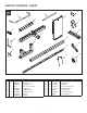
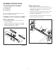
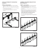
ASSEMBLE THE BLADE MOUNT ASSEMBLY
STEP 3: (SEE FIGURE 3)
• Attach four pivot brackets (5) to the blade mount
assembly (7) using four hex bolts (G) and Nylock hex
nuts (N).
• To help align the pivot brackets (5), temporarily insert
the pivot shaft (8) through the holes in the pivot
brackets.
• Remove the pivot shaft (8) once the pivot brackets (5)
are securely attached to the blade mount assembly (7).
G
5
5
N
8
5
7
FIGURE 3
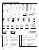
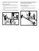
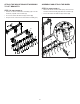
ATTACH THE BLADE MOUNT ASSEMBLY TO
THE HITCH MOUNT ASSEMBLY
STEP 4: (SEE FIGURE 4)
• Insert the blade mount assembly (7) into the hitch
mount assembly tube (6).
• Secure with a clevis pin (I) and a hair cotter pin (K).
• Insert the square plugs (ZZ) into the blade mount
assembly (7).
7
6
K
ZZ
I
FIGURE 4