
User Manual

5
TOOLS REQUIRED FOR ASSEMBLY
(1) Adjustable Wrench
(2) 7/16" Wrenches
(2) 1/2" Wrenches
(2) 9/16" Wrenches
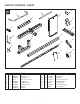
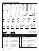
Lay out and identify the parts and hardware using the
illustrations on page 3 and page 4.
ASSEMBLE THE HITCH MOUNT ASSEMBLY
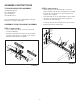
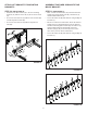
STEP 1: (SEE FIGURE 1)
• Insert a slider tube (2) into each end of the hitch
mount assembly (6).
• Attach the slider tube to the hitch mount assembly
using two hex bolts (G), four washers (V), and two
Nylock hex nuts (N). Do not tighten.
2
2
6
N
V
G
V
FIGURE 1
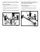
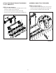
STEP 2: (SEE FIGURE 2)
• Attach the hitch mount assembly (6) to the tractor
frame using two U-bolts (4) secured with two mounting
brackets (3), four washers (U), and four Nylock hex
nuts(P). Do not tighten.
• If the slider tube does not fully extend into both U-bolts
(4), then loosen the appropriate hex bolt (G) and
reposition the slider tube (2).
• Center the hitch mount assembly on the tractor frame.
• Tighten all hex bolts and hex nuts.
2
6
4
3
U
P
G
FIGURE 2
ASSEMBLY INSTRUCTIONS