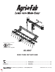
Want more information or assembly tips? Video Instruction Guide youtube.com/c/agrifab 45-0597 Zero Turn DeThaTcher ...................................................................3 FranÇaIS ....................................................... 16 enGLISh............................................................4 eSPaÑoL.........................................................21 the fastest way to purchase parts www.speedepart.com FORM NO.
SaFeTY ruLeS Remember, any equipment can cause injury if operated improperly or if the user does not understand how to operate the equipment. Exercise caution at all times when using this equipment. cauTIon: VehIcLe BraKInG anD STaBILITY MaY Be aFFecTeD WITh The aDDITIon oF an acceSSorY or an aTTachMenT. Be aWare oF chanGInG conDITIonS on SLoPeS. LooK For ThIS SYMBoL To PoInT ouT IMPorTanT SaFeTY PrecauTIonS. IT MeanS - aTTenTIon! BecoMe aLerT! Your SaFeTY IS InVoLVeD.
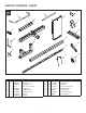
carTon conTenTS - ParTS 10 8 9 1 2 11 3 12 6 13 4 7 16 14 5 17 15 reF QTY 1 2 3 4 5 6 7 8 9 2 2 2 2 4 1 1 1 1 ParT no 45823BL3 45814BL3 45908BL3 45909 45816BL3 69643BL3 69642BL3 45817BL3 2-446BL3 DeScrIPTIon reF QTY Push Tube Slider Tube Mounting Bracket U-Bolt, 7.0 X 3.
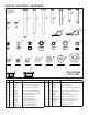
carTon conTenTS - harDWare H C A D E F I G B J L M N O K P Q R Y S T Z reF QTY A B C D E F G H I J K L M N 10 12 2 2 1 2 6 2 1 2 5 12 14 6 ParT no 43182 43012 47024 47407 45100 43224 43432 43023 HA23636 43055 43343 47189 47810 HA21362 U V W X ZZ noT ShoWn FuLL SIZe DeScrIPTIon reF QTY Bolt, Hex 5/16-18 X 3/4 GR5 Bolt, Hex 1/4-20 X 3/4 GR5 Bolt, Hex 1/2-13 X 4-1/2 GR5 Bolt, Hex 5/16-18 X 4 GR5 Bolt, Hex 1/2-13 X 4 GR5 FT Bolt, Hex 5/16-18 X 2-1/4 GR5 Bolt, Hex 3/8-16 X 2-1/2 GR5
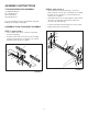
aSSeMBLY InSTrucTIonS STeP 2: (See FIGure 2) TooLS reQuIreD For aSSeMBLY (1) Adjustable Wrench (2) 7/16" Wrenches (2) 1/2" Wrenches (2) 9/16" Wrenches Lay out and identify the parts and hardware using the illustrations on page 3 and page 4. aSSeMBLe The hITch MounT aSSeMBLY • Attach the hitch mount assembly (6) to the tractor frame using two U-bolts (4) secured with two mounting brackets (3), four washers (U), and four Nylock hex nuts (P). Do not tighten.
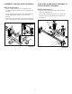
aSSeMBLe The BLaDe MounT aSSeMBLY aTTach The BLaDe MounT aSSeMBLY To The hITch MounT aSSeMBLY STeP 3: (See FIGure 3) • • • Attach four pivot brackets (5) to the blade mount assembly (7) using four hex bolts (G) and Nylock hex nuts (N). STeP 4: (See FIGure 4) • Insert the blade mount assembly (7) into the hitch mount assembly tube (6). To help align the pivot brackets (5), temporarily insert the pivot shaft (8) through the holes in the pivot brackets.
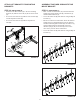
aTTach The BuLKheaD To The BLaDe MounT aSSeMBLY aTTach PuSh TuBeS To The BuLKheaD STeP 5: (See FIGure 5) • With a push tube (1) level to the hitch mount assembly (6), insert the uncapped end of the push tube into the bulkhead (9) hole at that height. • Repeat with the second push tube (1). • Secure each push tube (1) to the bulkhead (9) using a washer (Y) and hair cotter pin (K).
STeP 7: (See FIGure 7) • • • aSSeMBLe SQuare TuBe To BuLKheaD Attach the two push tubes (1) together using a clevis pin (H) and a spacer (R) between the push tubes at the end closest to the bulkhead (9). STeP 8: (See FIGure 8) Insert a second clevis pin (H) through the opposite side of the push tubes at the end furthest from the bulkhead (9). • Attach the square tube (13) to the bulkhead (9) using two hex bolts (F), washers (X) and hex nuts (M).
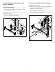
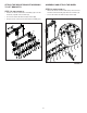
aTTach LIFT BracKeTS To MounTInG BracKeTS aSSeMBLe ThaTcher SPrInGS To TIne MounT BracKeT STeP 10: (See FIGure 10) • Attach the two lift brackets (12) to the two mounting brackets (11) with the two bolts (C) above the two bolts (D). STeP 11: (See FIGure 11) • Onto one tine mount bracket (14), attach six thatcher springs (15) using six hex bolts (B), six washers (T), and six rubber washers (S). • Secure the two hex bolts (C) with the four washers (W) and two Nylock hex nuts (O).
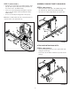
aTTach TIne MounT BracKeT aSSeMBLY To LIFT BracKeTS aSSeMBLe anD aTTach The WheeL STeP 12: (See FIGure 12) • Attach the wheel mount bracket (16) to the front tine mount bracket assembly (14) with two hex bolts (A). • Secure the hex bolts with two Nylock nuts (M). • STeP 13: (See FIGure 13) Attach one tine mount bracket assembly (14) to the lift brackets (14) with four hex bolts (A). • Secure the hex bolts with four Nylock nuts (M). • Repeat for the other tine mount bracket assembly (14).
STeP 14: (See FIGure 14) • • oPeraTIon Attach the wheel (17) to the wheel mount bracket (16) using a hex bolt (E), two washers (W), a hex nut (Q), and a Nylock hex nut (O). cauTIon: Failure to obey the following cautions could result in personal injury or product damage: • Securely position your feet on the push tube handles when engaging or disengaging the dethatcher.
enGaGe The DeThaTcher aSSeMBLY DISenGaGe The DeThaTcher aSSeMBLY 1. 1. Sit on the tractor so that your feet can reach the push tube handles. Sit on the tractor so that your feet can reach the push tube handles. 2. When disengaging the dethatcher, be prepared to push the weight of the dethatcher. 2. When engaging the dethatcher assembly, be prepared for the weight of the dethatcher to push against your feet. 3.
aDJuST The DeThaTcher heIGhT SToraGe NOTE: If using the dethatcher on uneven terrain, raise the dethatcher assembly one hole higher to prevent damage to the unit. To store, remove the dethatcher assembly from the hitch mount assembly. 1. Engage the dethatcher assembly so that the wheel is on the ground (see "Disengage the Dethatcher Assembly" on page 12). • Engage the dethatcher so that the wheel is on the ground. (See "Engage the Dethatcher Assembly" on page 12 for instructions.) 2.
rePaIr ParTS For 45-0597 Zero Turn DeThaTcher 14 8 22 11 8 27 31 10 30 29 10 14 7 18 29 22 25 32 22 11 7 31 14 30 14 34 33 9 27 11 11 14 25 27 33 32 7 36 35 42 25 11 2 20 19 12 27 37 43 x2 38 26 13 39 24 38 13 41 44 1 6 23 17 3 23 26 40 4 15 45 15 23 16 13 13 21 5 10 14 23
rePaIr ParTS For 45-0597 Zero Turn DeThaTcher reF QTY 1 2 3 4 5 6 7 8 9 10 11 12 13 14 15 16 17 18 19 20 21 22 23 10 12 2 2 1 2 6 2 1 2 5 12 14 6 3 8 1 1 12 12 8 4 6 ParT no 43182 43012 47024 47407 45100 43224 43432 43023 HA23636 43055 43343 47189 47810 HA21362 41657 43015 43019 23625 2-718 736-0142 43003 43081 R19171616 DeScrIPTIon reF QTY Bolt, Hex 5/16-18 X 3/4 GR5 Bolt, Hex 1/4-20 X 3/4 GR5 Bolt, Hex 1/2-13 X 4-1/2 GR5 Bolt, Hex 5/16-18 X 4 GR5 Bolt, Hex 1/2-13 X 4 GR5 FT Bolt, Hex 5/16-18 X 2-1/4
rÈGLeS De SÉcurITÉ N’oubliez pas que tout équipement peut causer des blessures s’il est utilisé de manière incorrecte ou si l’utilisateur ne comprend pas comment l’utiliser. Faites preuve de prudence à tout moment lorsque vous utilisez cet équipement. rechercheZ ce SYMBoLe Pour SIGnaLer D’IMPorTanTeS PrÉcauTIonS De SÉcurITÉ. IL SIGnIFIe - FaITeS aTTenTIon! SoYeZ aLerTe! VoTre SÉcurITÉ eST en Jeu.
InSTrucTIonS D’aSSeMBLaGe FIXer L’aSSeMBLaGe Du MonTaGe De LaMe À L’aSSeMBLaGe Du MonTaGe D’aTTeLaGe ouTILS reQuIS Pour L’aSSeMBLaGe (1) Clé réglable (2) Clés 7/16 po (2) Clés 1/2 po ÉTaPe 4: (VoIr FIGure 4) (2) Clés 9/16 po Disposez et identifiez les pièces et le matériel à l'aide des illustrations à la page 3 et la page 4 • Insérez l’ensemble de montage de la lame (7) dans le tube de l’ensemble de montage de l’attelage (6). • Fixez avec un axe à épaulement (I) et une goupille bêta (K).
FIXer L’aSSeMBLaGe De SuPPorT De MonTaGe De DenTS auX SuPPorTS De LeVaGe aSSeMBLer Le TuBe À anGLe DroIT À La cLoISon ÉTaPe 8: (VoIr FIGure 8) • • Fixez le tube à angle droit (13) à la cloison (9) à l’aide de deux boulons à six pans (F), des rondelles (X) et des écrous à six pans (M). ÉTaPe 12: (VoIr FIGure 12) Insérez deux bouchons à angle droit (Z) dans le tube à angle droit.
FoncTIonneMenT DÉSenGaGer L’aSSeMBLaGe De DÉchauMeuSe (VoIr FIGure 16) 1. aTTenTIon : le non-respect des précautions suivantes peut entraîner des blessures ou des dommages au produit: • Placez vos pieds en toute sécurité sur les poignées du tube de poussée lorsque vous engagez ou désengagez la déchaumeuse. • Ne retirez PaS vos pieds des poignées de tube de poussée jusqu’à ce que la déchaumeuse soit complètement verrouillée en position de désengagement ou complètement relâchée en position d’engagement.
enTrePoSaGe MaInTenance (VoIr FIGure 18) (VoIr FIGure 19) Pour l’entreposage, retirer l’assemblage de déchaumeuse de l’assemblage de montage d’attelage. • Nettoyez l’assemblage de déchaumeuse après chaque utilisation. L’herbe et les feuilles humides ou mouillées endommageront l’assemblage du ressort de chaume si elles sont stockées pendant de longues périodes. • Vérifiez périodiquement le serrage des boulons.
norMaS De SeGurIDaD Recuerde que cualquier equipo puede causar lesiones si se utiliza incorrectamente, o si el usuario no sabe utilizarlo. Tenga cuidado en todo momento al usar este equipo. BuSQue eSTe SÍMBoLo Para IDenTIFIcar PrecaucIoneS De SeGurIDaD IMPorTanTeS. SIGnIFIca: ¡aTencIÓn! ¡eSTÉ aLerTa! Su SeGurIDaD eSTÁ en JueGo. aTencIÓn: acoPLar un acceSorIo o coMPLeMenTo a un VehÍcuLo PueDe aFecTar Su caPacIDaD De FrenaDo Y eSTaBILIDaD. eSTÉ aTenTo a LoS caMBIoS De conDIcIoneS en LaS PenDIenTeS.
InSTruccIoneS Para eL arMaDo acoPLaMIenTo DeL MonTaJe De La hoJa aL MonTaJe De enGanche herraMIenTaS neceSarIaS Para eL arMaDo (1) llave ajustable PaSo 4: (Ver FIGura 4) (2) llaves de 7/16" • Inserte el montaje de la hoja (7) en la barra del montaje de enganche (6). (2) llaves de 9/16" • Asegure con un pasador de chaveta (I) y un pasador de horquilla (K). Despliegue las piezas y los herrajes e identifíquelos guiándose por las ilustraciones en las páginas 3 y 4.
MonTaJe De La Barra cuaDraDa aL MaMParo MonTaJe De LoS SoPorTeS De MonTaJe De LoS DIenTeS arMaDoS a LoS SoPorTeS De eLeVacIÓn PaSo 8: (Ver FIGura 8) • • Fije la barra cuadrada (13) al mamparo (9) usando dos pernos hexagonales (F), arandelas (X) y tuercas hexagonales (M). PaSo 12: (Ver FIGura 12) Coloque los dos tapones cuadrados (Z) en los extremos de la barra.
FuncIonaMIenTo DeSenGanche DeL eScarIFIcaDor arMaDo (Ver FIGura 16) 1. aTencIÓn: no cumplir con las siguientes advertencias podría ocasionar lesiones personales o daños al producto: • Coloque los pies de forma segura sobre las manijas de la barra de empuje al enganchar o desenganchar el escarificador. • no quite los pies de las manijas de la barra de empuje hasta que el escarificador esté completamente trabado en la posición de desenganche, o completamente liberado en la posición de enganche.
aLMacenaMIenTo ManTenIMIenTo (Ver FIGura 18) • Siempre limpie el montaje de los resortes escarificadores después de cada uso. El césped y las hojas húmedos o mojados dañarán el montaje de los resortes, si queda guardado durante largos períodos sin usar. • Revise periódicamente si hay pernos sueltos. • Al comienzo de cada temporada, lubrique los puntos de pivote con un aceite liviano para máquinas. Para guardar, retire la unidad armada del montaje de enganche.
the fastest way to purchase parts www.speedepart.com rePaIr ParTS Agri-Fab, Inc. 809 South Hamilton Sullivan, IL. 61951 217-728-8388 www.agri-fab.com This document (or manual) is protected under the U.S. Copyright Laws and the copyright laws of foreign countries, pursuant to the Universal Copyright Convention and the Berne convention.