
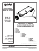
Product Manual


4
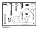
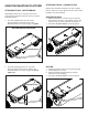
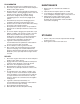
7. Secure the ends of the hitch tubes together using two
5/16 x 2-1/2" hex bolts (8) and 5/16" nylock nuts (14).
Do not tighten yet. See gure 3.
FIGURE 2
FIGURE 3
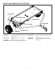
6. Attach the hitch tubes (5) to the third hole from the
front of the tray assembly using two 5/16 x 1" hex
bolts (11) and 5/16" nylock nuts (14). Do not tighten
yet. See gure 2.
8
8
14
11
11
14
14
5
5
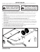
ASSEMBLY INSTRUCTIONS
ASSEMBLY OF SMARTLINK PLATFORM
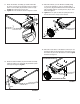
1. Rotate the end plates attached to the tray assembly
down to a vertical position as shown in gure 1.
2. Remove the bolt and nylock nut from the front right
corner of the tray assembly. See gure 1.
3. Attach the lift handle catch (6) to the front holes of the
tray assembly using the bolt and nylock nut removed
in step 1. See gure 1.
4. Assemble four 5/16 x 3/4" hex bolts (9) and 5/16"
nylock nuts (14) to the four empty corners in the tray
assembly. See gure 1.
5. Tighten all eight of the 5/16 x 3/4" hex bolts in the
corners of tray assembly.
TOOLS REQUIRED FOR ASSEMBLY
(2) 3/4" Wrenches
(2) 1/2" Wrenches
FIGURE 1
PRE-ASSEMBLED BOLT
6
9
14
PRE-ASSEMBLED NUT
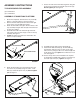
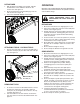
8. Assemble the grip (29) onto the lift handle (3).
9. Attach the lift tube assembly (2), the lift handle (3),
and the hitch tube (5) to the rear hole on the right
side of the tray using a 5/16 x 1-1/2" hex bolt (10) and
5/16" nylock nut (14). Tighten the nut then loosen 1/2
turn. See gure 4.
10. Secure the top hole of the lift handle to the top hole
of the lift tube assembly with a 5/16" x 1" hex bolt (11)
and 5/16" nylock nut (14). Tighten. See gure 4.
FIGURE 4
10
14
3
5
14
11
2
29