
Manual


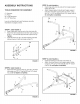


STEP 13: (SEE FIGURE 13)
* Fasten the hopper braces (11) to the hopper support
tubes using the nylock nuts (J) that were assembled
earlier. Do not tighten completely.
* Fasten the loose ends of the hopper braces to the
hitch tube using a 1/4" x 2" hex bolt (C) and a 1/4"
nylock nut (J). Do not tighten completely.
11
!
c
FIGURE 13
STEP 14:
• Tighten all bolts and nuts except for those shown in
step 10 that fasten the control bracket to the hitch tube.
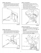
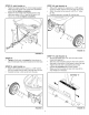
STEP 15: (SEE FIGURE 14)
• Slide a 5/8" washer (O), a spacer (L), a 5/8" washer
(O) and a wheel onto the end of the axle with no hole.
• Carefully hammer a hub cap (Z) onto the axle.
o
L
O
STEP 16: (SEE FIGURE 15)
* Slide a 5/8" washer (O), a spacer (L), a 5/8" washer
(O) and a wheel onto the end of the axle with a hole.
* Attach the wheel to the axle with a 3/16" x 2" cotter
pin (R).
* Carefully hammer a hub cap (Z) onto the axle.
FIGURE 15
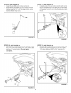
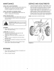
STEP 17: (SEE FIGURE 16)
• Set the adjustable stop at "5" and move the control
hande back against it.
• Slide the control bracket along the hitch tube until the
flow plate in the bottom of the hopper is open half way.
• Tighten the bolts and nuts fastening the control
bracket. Do not deform the control bracket.
• Make sure the flow plate will open and close all the
way. Readjust if necessary.
FIGURE 14
7
FIGURE 16