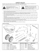
OWNERS MANUAL NOTICE D'UTILISATION MANUAL DEL USUARIO Model No. ModUle No. Modelo No. 45-04631 130 LB. TOW SPREADER I_PANDEUR CAUTION: Read Rules for Safe Operation ESPARCIDOR REMORQUi "== DE 130 LB. (59 KG) DE REMOLQUE DE 130 LBS. (59 KG) and Instructions Carefully ATTENTION: Lire et suivre attentivement tes instructions et consignes de securite de cette notice.
SAFETY RULES Remember, any power equipment can cause injury if operated improperly or if the user does not understand how to operate the equipment. Exercise caution at all times when using power equipment. Look for this symbol to point out important safety precautions. It means -ATTENTION! Become alert! Your safety is involved. • • • • • • • • • CAUTION: vehicle braking and stability may be affected with the addition of an accessory or an attachment. Be aware of changing conditions on slopes.
SHOWN FULL SIZE Z3 £ jE f f f f f f f f f f f f f f f f f f i i I R J I-- S O jL NOT SHOWN FULL SiZE J U W X Y HARDWARE PACKAGE REF A B C D E F G H I J K L M N QTY 1 2 2 6 2 1 2 1 2 13 1 2 9 5 PART NO 47623 49870 46699 1509-69 43648 43661 43840 49950 47810 47189 23625 48857 43088 1543-69 DESCRiPTiON REF QTY O 4 P 1 Q 1 R 1 S 1 T 1 U 1 V 1 W 2 X 1 Y 1 Z 2 AA 3 BB 1 Hitch Pin Hex Hex Hex Hex Hex Hex Bolt, Bolt, Bolt, Bolt, Bolt, Bolt, 1/4" x 2-1/2" 1/4" x 2" 1/4" x 1-3/4" 1/4" x 1-1/2" 1/
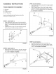
ASSEMBLY iNSTRUCTiONS STEP 3: (SEE FIGURE 3) * TOOLS (1) (!) (2) (2) REQUIRED FOR ASSEMBLY o Hammer Pliers 7/16" Wrenches 1/2" Wrenches insert plugs (AA) into the ends of the hopper support tubes (5) and (6). Attach hopper support tube (5) and hopper support tube (6) to the hitch support tubes as shown, using two 1/4" x 1-1/2" hex bolts (E) and 1/4" nylock nuts (J). Do not tighten completely. AA / Lay out and identify parts and hardware using the illustrations on pages 2 and 3.
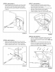
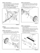
STEP 5: (SEE FIGURE 5) STEP 7: (SEE FIGURE 7) * * install the gearbox by inserting the end of the verticle shaft into the cross brace bushing and inserting the axle into the ends of the hopper support tubes. Be sure the hole in the axle is located on the side shown in figure 5. Place the hopper on the hopper support tubes, inserting the spreader shaft up through the square hole in the bottom of the hopper. Slide the hopper bushing (X) onto the spreader shaft and insert it into the bottom of the hopper.
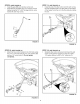
STEP 9: (SEE FIGURE 9) STEP 11: (SEE FIGURE 11) * * • Install the grip (BB) onto the flow control arm. Assemble the adjustable stop (V) to the flow control bracket using the 1/4" x 3/4" carriage bolt (H), nylon washer (N) and wing nut (U). Install the end of the flow control rod (10) with no hole into the elongated hole in the flow plate on the bottom of the hopper. Lock the rod in the flow plate by rotating the rod.
STEP 13: (SEE FIGURE 13) STEP 16: (SEE FIGURE 15) * * * Fasten the hopper braces (11) to the hopper support tubes using the nylock nuts (J) that were assembled earlier. Do not tighten completely. Fasten the loose ends of the hopper braces to the hitch tube using a 1/4" x 2" hex bolt (C) and a 1/4" nylock nut (J). Do not tighten completely. * * Slide a 5/8" washer (O), a spacer (L), a 5/8" washer (O) and a wheel onto the end of the axle with a hole.
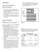
OPERATION HOW TO USE YOUR SPREADER 10. Heavy moisture conditions may' require use of a vinyl hopper cover to keep contents dry'.The cover acts as a wind and moisture shield, but should not be used as a rain cover. The #41316 cover can be ordered as an option. See pages 18 and 19. SETTING THE FLOW CONTROL (Refer to figure 16 on page 7.) 1. 2. 3. Loosen the wing nut, set the adjustable stop to the desired flow rate setting and retighten the wing nut.
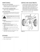
MAINTENANCE CHECK FOR LOOSE FASTENERS 1. Before each use, make a thorough visual check of the spreader for any bolts and nuts which may have loosened. Retighten any loose bolts and nuts. CHECK FOR WORN OR DAMAGED PARTS 2. Check for worn or damaged parts before each use. Repair or replace parts if necessary. CHECK TiRE iNFLATiON 3. Check if tires are adequately inflated before each use. Do not inflate tires beyond maximum recommended pressure on tire.
CONSIGNES DE Si CURITI N'oubtiez pas qu'un materiet motorise peut causer des btessures s'il est mal utilise ou si son utilisateur ne comprend pas comment s'en servir. Agissez avec precaution en permanence quand vous utilisez un materiet motorise. ATTENTION : Le freinage et la stabilite du vehicules risquent d'etre affectees par I'ajout d'un accessoire. Ayez conscience des conditions changeantes sur les pentes. Ce symbote indique les precautions de securite importantes.
#:TAPE 3 : (VOIR LA FIGURE 3) • Inserez les obturateurs (AA) dans les extremites des tubessupports de ta tremie (5) et (6). • Fixez tes tubes-support d'attetage (5) et (6) de la tremie aux tubes-support d'attelage, & I'aide de deux boutons hexagonaux de 1/4 pox 1-1/2 po (E) et ecrous autofreines de 1/4 po (J). Ne serrez pas completement.
UTILISATION COMMENT UTILISER REGLAGE DU DEBIT VOTRE #:PANDEUR 10. Par forte humidite, il pourra _tre necessaire d'utiliser un couvercle en vinyle sur la tremie pour garder son chargement au sec. Le couvercle protege contre le vent et I'humidite, mais n'est pas prevu pour proteger de ta pluie. On peut commander le couvercle N ° 41316 en option. Voir les pages 18 et 19. A¢:RATEUR (Reportez-vous & la figure 16 de la page 7) 1.
ENTRETIEN SERVICE VI_RIFIEZ LE BON SERRAGE DE LA VISSERIE 1. 1. Avant chaque utilisation, effectuez une verification visuelle approfondie de t'epandeur, pour verifiez qu'aucun bouton ou ecrou n'est desserre. Resserrez tout boulon ou ecrou eventuellement desserre. VERIFIEZ QU'AUCUNE ENDOMMAG#E 2. PI#CE N'EST USEE OU Verifiez avant chaque utilisation qu'aucune piece n'est usee ou endommagee. Reparez ou remplacez les pieces, le cas 6cheant.
REGLAS DE SEGURIDAD Recuerde que los equipos etectricos pueden causar lesiones si no se operan correctamente equipo. PRECAUCION: El sistema de freno y la estabitidad det vehfculo pueden verse afectados con ta adici6n de un accesorio. Preste atencion alas condiciones cambiantes en tas pendientes. Preste atenci6n a este simboto ya que indica precauciones de seguridad importantes. Significa -- iatenci6n! iEste alerta! Su seguridad est,. en juego.
PASO 2: (VEA LA FIGURA 2) • Acopte los tubos de soporte (4) e (3) det enganche al tubo de soporte usando un perno hexagonal de 1/4 putg. x 2 putg. (C) y tuerca de cierre de nylon de 1/4 pulg. (J). No apriete completamente. PASO 10: (VEA LA FIGURA 10) • Acopte el soporte de control de flujo al tubo de la totva usando dos pemos hexagonales de 1/4 pulg. x 1-3/4 putg. (D), cuatro arandelas de 1/4 putg. (M) y dos tuercas de cierre de nylon 1/4 pulg. (J). No apriete completamente.
OPERACl6N 10. En condiciones de bastante humedad puede requerirse et uso de una cubierta de vinilo para totva a fin de que et contenido se mantenga seco. La cubierta funciona como un protector contra et viento y la humedad, pero no debe usarse como cubierta para proteger contra la Iluvia. Como opci6n, puede hacer un pedido de la cubierta #41316. Vea las pdtginas 18 y 19. FORMA DE USAR EL ESPARCIDOR GRADUACION DEL CONTROL DE FLUJO (Refierase a la figura 16 en ta pdtgina 7) 1.
iViANTENllVllENTO SERVlCIO Y AJUSTES VERIFIQUE QUE NO HAYAN SUJETADORES 1. 1. Antes de cada uso, haga una inspecci6n visual compteta det esparcidor para verificar que no hayan pernos y tuercas flojos. Vuetva a ajustar los pernos y tuercas flojos. VERIFIQUE DANADAS 2. FLOJOS QUE NO HAYAN PIEZAS GASTADAS O Verifique que no hayan piezas gastadas o dafiadas antes de cada uso. Repare o cambia las piezas si es necesario. NOTA" El soporte transversal no se muestra para hacer mAs clara la ilustraci6n.
REPAIR PARTS FOR 45-04631 /_ / 33 32 @ 28 3 / 11 40 2 // 45 / 37 54 48 16 6_ \ 25 52 46 .._ 53-_ 21 .._..
REPAIR PARTS FOR 45-04631 130 LB.
REPAIR PARTS Agri-Fab, Inc. 809 South Hamilton Sullivan, IL. 61951 217-728-8388 www.agri-fab.com This document (or manual) is protected under the U.S. Copyright Laws and the copyright laws of foreign countries, pursuant to the Universal Copyright Convention and the Berne convention.