
User Manual


6
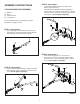
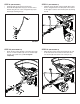
STEP 10: (SEE FIGURE 10)
• Attach the ow control bracket to the hitch tube using
two 1/4" x 1-3/4" hex bolts (D), four 1/4" washers (M)
and two 1/4" nylock nuts (J). Do not tighten
completely.
FIGURE 10
FIGURE 9
STEP 9: (SEE FIGURE 9)
• Install the grip (T) onto the ow control arm.
• Assemble the adjustable stop (V) to the ow control
bracket using the 1/4" x 3/4" carriage bolt (G), nylon
washer (N) and wing nut (U).
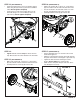
STEP 11: (SEE FIGURE 11)
• Install the end of the ow control rod (10) with no hole
into the elongated hole in the ow plate on the bottom
of the hopper. Lock the rod in the ow plate by rotating
the rod.
FIGURE 11
FIGURE 12
STEP 12: (SEE FIGURE 12)
• Swing the ow control rod around and insert the end
of the rod into the ow control arm. Secure it with a
1/4" washer (M) and a 3/32" x 3/4" cotter pin (P).
D
J
M
M
M
P
U
N
V
G
T