
User Manual


4
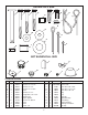
ASSEMBLY INSTRUCTIONS
FIGURE 2
TOOLS REQUIRED FOR ASSEMBLY
(1) Hammer
(1) Pliers
(2) 7/16" Wrenches
(2) 1/2" Wrenches
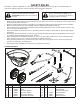
Lay out and identify parts and hardware using the
illustrations on pages 2 and 3.
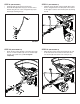
STEP 2: (SEE FIGURE 2)
• Attach the hitch support tubes (3), and (4) to the hitch
tube using one 1/4" x 2" hex bolt (C) and 1/4" nylock
nut (J). Do not tighten completely.
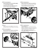
STEP 3: (SEE FIGURE 3)
• Insert the hex bushings (W) into the ends of the
hopper support tubes (5).
• Assemble the axle/gearbox assembly and hopper
support tubes (5) to the hitch support tubes as shown,
using two 1/4" x 2" hex bolts (C), spacers (E), and 1/4"
nylock nuts (J). Do not tighten completely.
C
J
4
3
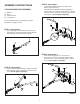
FIGURE 3
FIGURE 1
STEP 1: (SEE FIGURE 1)
• Insert a plug (S) into the end of the hitch tube (9).
• Install the hitch pin (A) in the hitch bracket and hitch
tube and secure it with the hairpin cotter (H).
A
H
S
9
STEP 4: (SEE FIGURE 4)
• Insert the bushing (Y) into the cross brace (7).
• Attach the cross brace to the hopper support tubes
using two 1/4" x 2-1/2" hex bolts (B) and 1/4" nylock
nuts (J). Do not tighten completely.
FIGURE 4
E
J
E
J
W
C
C
W
5
5
J
J
B
B
Y
7