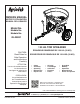
™ OWNERS MANUAL NOTICE D’UTILISATION MANUAL DEL USUARIO Model No. Modèle No. Modelo No. 45-04631 130 LB. Tow Spreader CAUTION: Read Rules for Safe Operation and Instructions Carefully ATTENTION: Lire et suivre attentivement les instructions et consignes de sécurité de cette notice. PRECAUCION: Lea cuidadosamente los Procedimientos e Instrucciones para la Operación Segura de la Máquina. ÉPANDEUR REMORQUÉ DE 130 LB. (59 KG) ESPARCIDOR DE REMOLQUE DE 130 LBS.
SAFETY RULES Remember, any power equipment can cause injury if operated improperly or if the user does not understand how to operate the equipment. Exercise caution at all times when using power equipment. CAUTION: vehicle braking and stability may be affected with the addition of an accessory or an attachment. Be aware of changing conditions on slopes. Look for this symbol to point out important safety precautions. It means — ATTENTION! Become alert! Your safety is involved.
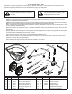
SHOWN FULL SIZE I A B C D E F G H J P Q N R M S O T L K NOT SHOWN FULL SIZE U W V AA Z X Y BB HARDWARE PACKAGE REF QTY A 1 B 2 C 2 D 6 E 2 F 1 G 2 H 1 I 2 J 13 K 1 L 2 M 9 N 5 PART NO 47623 49870 46699 1509-69 43648 43661 43840 49950 47810 47189 23625 48857 43088 1543-69 DESCRIPTION REF QTY PART NO DESCRIPTION O 4 R19212016 Washer, 5/8" P 1 44101 Cotter Pin, 3/32" x 3/4" Q 1 43093 Cotter Pin, 1/8" x 1-1/2" R 1 46855 Cotter Pin, 3/16" x 2" S 1 48934 Hairpin, Agitator T 1 43343 Hairpin
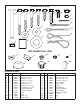
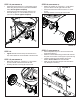
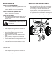
ASSEMBLY INSTRUCTIONS STEP 3: (SEE FIGURE 3) TOOLS REQUIRED FOR ASSEMBLY • (1) (1) (2) (2) • Hammer Pliers 7/16" Wrenches 1/2" Wrenches Insert plugs (AA) into the ends of the right hand (6) and left hand (5) hopper support tubes. Attach the right hand and left hand hopper support tubes to the hitch support tubes using two 1/4" x 1-1/2" hex bolts (E) and 1/4" nylock nuts (J). Do not tighten completely. AA 5 Lay out and identify parts and hardware using the illustrations on pages 2 and 3.
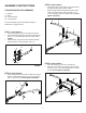
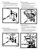
STEP 5: (SEE FIGURE 5) • STEP 7: (SEE FIGURE 7) Install the gearbox by inserting the end of the verticle shaft into the cross brace bushing and inserting the axle into the ends of the hopper support tubes. Be sure the hole in the axle is located on the side shown in figure 5. • • • • Place the hopper on the hopper support tubes, inserting the spreader shaft up through the square hole in the bottom of the hopper.
STEP 11: (SEE FIGURE 11) STEP 9: (SEE FIGURE 9) • • • Install the grip (BB) onto the flow control arm. Assemble the adjustable stop (V) to the flow control bracket using the 1/4" x 3/4" carriage bolt (H), nylon washer (N) and wing nut (U). Install the end of the flow control rod (10) with no hole into the elongated hole in the flow plate on the bottom of the hopper. Lock the rod in the flow plate by rotating the rod.
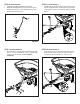
STEP 13: (SEE FIGURE 13) • STEP 16: (SEE FIGURE 15) Fasten the hopper braces (11) to the hopper support tubes using the nylock nuts (J) that were assembled earlier. Do not tighten completely. Fasten the loose ends of the hopper braces to the hitch tube using a 1/4" x 2" hex bolt (C) and a 1/4" nylock nut (J). Do not tighten completely. • • • • Slide a 5/8" washer (O), a spacer (L), a 5/8" washer (O) and a wheel onto the right side of the axle.
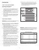
OPERATION 10. Heavy moisture conditions may require use of a vinyl hopper cover to keep contents dry. The cover acts as a wind and moisture shield, but should not be used as a rain cover. The #41316 cover can be ordered as an option. See pages 18 and 19. HOW TO USE YOUR SPREADER SETTING THE FLOW CONTROL (Refer to figure 16 on page 7.) 1. Loosen the wing nut, set the adjustable stop to the desired flow rate setting and retighten the wing nut.
MAINTENANCE SERVICE AND ADJUSTMENTS CHECK FOR LOOSE FASTENERS 1. Before each use, make a thorough visual check of the spreader for any bolts and nuts which may have loosened. Retighten any loose bolts and nuts. 1. If the axle and gear assembly is disassembled, mark down the positions of the parts as they are removed. The drive wheel and large gear positions, in relation to the small gear, determine which direction the impeller will spin. Be sure to reassemble them in their original positions.
FRANÇAIS CONSIGNES DE SÉCURITÉ N’oubliez pas qu’un matériel motorisé peut causer des blessures s’il est mal utilisé ou si son utilisateur ne comprend pas comment s’en servir. Agissez avec précaution en permanence quand vous utilisez un matériel motorisé. ATTENTION : Le freinage et la stabilité du véhicules risquent d’être affectées par l’ajout d’un accessoire. Ayez conscience des conditions changeantes sur les pentes. Ce symbole indique les précautions de sécurité importantes.
ÉTAPE 3 : (VOIR LA FIGURE 3) ÉTAPE 10 : (VOIR LA FIGURE 10) • • • Insérez les obturateurs (AA) dans les extrémités des tubessupports gauche de la trémie (5). Fixez les tubes-support d’attelage droit et gauche de la trémie aux tubes-support d’attelage, à l’aide de deux boulons hexagonaux de 1/4 po x 1-1/2 po (E) et écrous autofreinés de 1/4 po (J). Ne serrez pas complètement. ÉTAPE 11 : (VOIR LA FIGURE 11) • ÉTAPE 4 : (VOIR LA FIGURE 4) • • Insérez la bague (Y) dans le support transversal (7).
UTILISATION 10. Par forte humidité, il pourra être nécessaire d’utiliser un couvercle en vinyle sur la trémie pour garder son chargement au sec. Le couvercle protège contre le vent et l’humidité, mais n'est pas prévu pour protéger de la pluie. On peut commander le couvercle N° 41316 en option. Voir les pages 18 et 19. COMMENT UTILISER VOTRE ÉPANDEUR AÉRATEUR RÉGLAGE DU DÉBIT (Reportez-vous à la figure 16 de la page 7) 1.
ENTRETIEN SERVICE ET RÉGLAGES 1. VÉRIFIEZ LE BON SERRAGE DE LA VISSERIE 1. Avant chaque utilisation, effectuez une vérification visuelle approfondie de l’épandeur, pour vérifiez qu’aucun boulon ou écrou n’est desserré. Resserrez tout boulon ou écrou éventuellement desserré. V É R I F I E Z Q U ’ AU C U N E P I È C E N ’ E S T U S É E O U ENDOMMAGÉE 2. Vérifiez avant chaque utilisation qu’aucune pièce n’est usée ou endommagée. Réparez ou remplacez les pièces, le cas échéant.
ESPAÑOL REGLAS DE SEGURIDAD Recuerde que los equipos eléctricos pueden causar lesiones si no se operan correctamente o si el usuario no sabe cómo operar el equipo. PRECAUCIÓN: El sistema de freno y la estabilidad del vehículo pueden verse afectados con la adición de un accesorio. Preste atención a las condiciones cambiantes en las pendientes. Preste atención a este símbolo ya que indica precauciones de seguridad importantes. Significa — ¡atención! ¡Esté alerta! Su seguridad está en juego.
PASO 2: (VEA LA FIGURA 2) PASO 10: (VEA LA FIGURA 10) • • Acople los tubos de soporte derecho (4) e izquierdo (3) del enganche al tubo de soporte usando un perno hexagonal de 1/4 pulg. x 2 pulg. (C) y tuerca de cierre de nylon de 1/4 pulg. (J). No apriete completamente. Acople el soporte de control de flujo al tubo de la tolva usando dos pernos hexagonales de 1/4 pulg. x 1-3/4 pulg. (D), cuatro arandelas de 1/4 pulg. (M) y dos tuercas de cierre de nylon 1/4 pulg. (J). No apriete completamente.
OPERACIÓN 10. En condiciones de bastante humedad puede requerirse el uso de una cubierta de vinilo para tolva a fin de que el contenido se mantenga seco. La cubierta funciona como un protector contra el viento y la humedad, pero no debe usarse como cubierta para proteger contra la lluvia. Como opción, puede hacer un pedido de la cubierta #41316. Vea las páginas 18 y 19. FORMA DE USAR EL ESPARCIDOR GRADUACION DEL CONTROL DE FLUJO (Refiérase a la figura 16 en la página 7) 1.
MANTENIMIENTO SERVICIO Y AJUSTES VERIFIQUE QUE NO HAYAN SUJETADORES FLOJOS 1. 1. Antes de cada uso, haga una inspección visual completa del esparcidor para verificar que no hayan pernos y tuercas flojos. Vuelva a ajustar los pernos y tuercas flojos. VERIFIQUE QUE NO HAYAN PIEZAS GASTADAS O DAÑADAS 2. Verifique que no hayan piezas gastadas o dañadas antes de cada uso. Repare o cambia las piezas si es necesario. NOTA: El soporte transversal no se muestra para hacer más clara la ilustración.
REPAIR PARTS FOR 45-04631 130 LB.
REPAIR PARTS FOR 45-04631 130 LB.
the fastest way to purchase parts www.speedepart.com REPAIR PARTS Agri-Fab, Inc. 809 South Hamilton Sullivan, IL. 61951 217-728-8388 www.agri-fab.com This document (or manual) is protected under the U.S. Copyright Laws and the copyright laws of foreign countries, pursuant to the Universal Copyright Convention and the Berne convention.