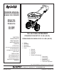
™ OWNERS MANUAL NOTICE D’UTILISATION MANUAL DEL USUARIO Model No. Modèle No. Modelo No. 45-0462 45-0471 130 LB. Push Spreader CAUTION: Read Rules for Safe Operation and Instructions Carefully ATTENTION: Lire et suivre attentivement les instructions et consignes de sécurité de cette notice. PRECAUCION: Lea cuidadosamente los Procedimientos e Instrucciones para la Operación Segura de la Máquina. ÉPANDEUR POUSSÉ DE 130 LB. (59 KG) ESPARCIDOR DE EMPUJE DE 130 LBS.
SAFETY RULES CAUTION: VEHICLE BRAKING AND STABILITY MAY BE AFFECTED WITH THE ADDITION OF AN ACCESSORY OR AN ATTACHMENT. BE AWARE OF CHANGING CONDITIONS ON SLOPES. LOOK FOR THIS SYMBOL TO POINT OUT IMPORTANT SAFETY PRECAUTIONS. IT MEANS — ATTENTION! BECOME ALERT! YOUR SAFETY IS INVOLVED. The following safety precautions are suggested.
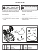
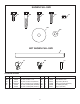
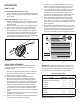
SHOWN FULL SIZE AA DD BB EE GG FF HH NOT SHOWN FULL SIZE II JJ KK LL HARDWARE PACKAGE REF QTY AA 2 BB 2 DD 1 EE 2 FF 4 5 PART NO 47856 43648 43012 HA23740 47189 47189 DESCRIPTION REF QTY Screw, 5/16 x 3/4" Thd. Form GG 1 Bolt, Hex 1/4-20 x 1-1/2 HH 2 Bolt, Hex 1/4-20 x 3/4 (45-0471) II 1 Screw, 1/4-20 Thd.
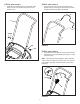
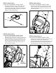
ASSEMBLY INSTRUCTIONS STEP 3: (SEE FIGURE 3) THIS STEP FOR MODEL 45-0471 ONLY TOOLS REQUIRED FOR ASSEMBLY • (1) Hammer (2) 7/16" Wrenches (1) Knife or Scissors Lay out and identify parts and hardware using the illustrations on pages 2 and 3. HINT: The less soap left in the grip, the sooner the grip will dry and become snug on the handle. STEP 1: (SEE FIGURE 1) • Apply liquid soap to the inside of the foam grip (II). Work the soap down the length of the grip to coat the inside.
STEP 4: (SEE FIGURE 4) • STEP 5: (SEE FIGURE 5) Assemble the handle tube (D) to the hopper tubes using two 5/16 x 3/4 screws (AA) and 5/16" lock washers (HH). • Insert the ends of the flow control bail (E) into the handle tube (D), inserting the bent end first. The bail should pull back freely against the handle. E D AA HH D HH FIGURE 5 AA STEP 6: (SEE FIGURE 6) • • Insert the end of the cable into the flow control bail (E). Attach the flow control assembly (B) using two 1/4-20 nylock nuts (FF).
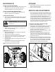
STEP 7: (SEE FIGURE 7) THIS STEP FOR MODEL 45-0471 ONLY • STEP 9: (SEE FIGURE 9) THIS STEP FOR MODEL 45-0471 ONLY Assemble the deflector rod (I), washer (GG), and connecting rod (H) to the deflector (F) using the thread forming screw (EE). Tighten the screw until it is just snug and then back it off 1/4 turn or until the deflector rod (H) will slide freely. • Attach the push rod clamp (JJ) and the eye clamp (KK) to the right side of the handle tube.
OPERATION 7. If fertilizer is accidentally deposited too heavily in a small area, soak the area thoroughly with a garden hose or sprinkler to prevent burning of the lawn. 8. To insure uniform coverage, make each pass so that the broadcast pattern slightly overlaps the pattern from the previous pass as shown in figure 12. The approximate broadcast widths for different materials are shown in the application chart on this page. 9.
MAINTENANCE STORAGE CHECK FOR LOOSE FASTENERS 1. Before each use, make a thorough visual check of the spreader for any bolts and nuts which may have loosened. Retighten any loose bolts and nuts. 1. Rinse inside of hopper and exterior of spreader and allow to dry before storing. 2. Store in a clean, dry area. SERVICE AND ADJUSTMENTS CHECK FOR WORN OR DAMAGED PARTS 2. Check for worn or damaged parts before each use. Repair or replace parts if necessary. 1.
BLANK PAGE 9
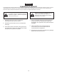
FRANÇAIS CONSIGNES DE SÉCURITÉ Les précautions de sécurité ci-dessous sont suggérées. Cet épandeur centrifuge a été conçu, fabriqué et essayé afin d’offrir un service raisonnablement sûr et efficace, sous réserve qu’il soit exploité en stricte conformité avec ces instructions. Le non respect de ces instructions risque d’entraîner des blessures. Toujours respecter les règles d’exploitation en sécurité.
INSTRUCTIONS DE MONTAGE ÉTAPE 7 : (VOIR LA FIGURE 7) CETTE ÉTAPE NE S’APPLIQUE QU’AU MODÈLE 45-0471 • OUTILS NÉCESSAIRE POUR LE MONTAGE (1) Marteau (2) Clefs de 7/16 po (1) Couteau ou paire de ciseaux ÉTAPE 8 : (VOIR LA FIGURE 8) CETTE ÉTAPE NE S’APPLIQUE QU’AU MODÈLE 45-0471 Étalez et identifiez les pièces et la quincaillerie à l’aide des illustrations des pages 2 et 3. • • ÉTAPE 1 : (VOIR LA FIGURE 1) • Retirez les écrous autofreinés de 1/4 po.
FONCTIONNEMENT 7. En cas de dépôt accidentel d’une grande quantité d’engrais sur une petite surface, bien imbiber celle-ci d’eau avec un tuyau d’arrosage ou un arroseur pour éviter une brûlure de la pelouse. 8. Pour assurer un épandage uniforme, effectuez chaque passe de sorte que sa couverture recouvre légèrement celle de la passe précédente, comme indiqué par la figure 12. Les largeurs approximatives de couverture pour différents produits sont indiquées dans le tableau d’application ci-contre. 9.
ENTREPOSAGE ENTRETIEN 1. VÉRIFIEZ LE BON SERRAGE DE LA VISSERIE 1. Avant chaque utilisation, effectuez une vérification visuelle approfondie de l’épandeur, pour vérifiez qu’aucun boulon ou écrou n’est desserré. Resserrez tout boulon ou écrou éventuellement desserré. 2. Rincer l’intérieur de la trémie et l’extérieur de l’épandeur, puis laisser sécher, avant de l’entreposer. Entreposer dans un local propre et sec. SERVICE ET RÉGLAGES VÉRIFIEZ QU’AUCUNE PIÈCE N’EST USÉE OU ENDOMMAGÉE 2.
ESPAÑOL REGLAS DE SEGURIDAD Las siguientes precauciones de seguridad son sugerencias. Este esparcidor a voleo está diseñado, fabricado y probado para ofrecer un servicio seguro y efectivo, siempre que sea operado siguiendo estrictamente estas instrucciones. El no hacerlo así puede resultar en lesiones personales. Siempre siga estas normas de operación segura. Precaución: el sistema de freno y la estabilidad del vehículo pueden verse afectados con la adición de un accesorio.
INSTRUCCIONES DE ENSAMBLAJE PASO 7: (VEA LA FIGURA 7) ESTE PASO ES PARA EL MODELO 45-0471 SOLAMENTE • HERRAMIENTAS REQUERIDAS PARA EL ENSAMBLAJE (1) Martillo (2) Llaves de 7/16 pulg. (1) Cuchillo o tijera PASO 8: (VEA LA FIGURA 8) ESTE PASO ES PARA EL MODELO 45-0471 SOLAMENTE Despliegue e identifique las partes y la tornillería utilizando las ilustraciones en las páginas 2 y 3. • • PASO 1: (VEA LA FIGURA 1) • Retire las tuercas de cierre de nylon de 1/4 de pulg.
OPERACIÓN 8. Para asegurar una cobertura uniforme, haga cada pase de manera que el patrón de voleo se sobreponga livianamente al patrón del pase previo como se muestra en la figura 12. El ancho de voleo aproximado para diferentes materiales se muestra en la tabla de aplicación de esta página. 9. Al volear fertilizantes para el control de hierba mala, asegúrese de que el patrón de voleo no llegue a los árboles, flores ni arbustos verdes perennes.
ALMACENAMIENTO MANTENIMIENTO 1. VERIFIQUE QUE NO HAYAN SUJETADORES FLOJOS 1. Antes de cada uso, haga una inspección visual completa del esparcidor para verificar que no hayan pernos y tuercas flojos. Vuelva a ajustar los pernos y tuercas flojos. 2. VERIFIQUE QUE NO HAYAN PIEZAS GASTADAS O DAÑADAS 2. Verifique que no hayan piezas gastadas o dañadas antes de cada uso. Repare o cambia las piezas si es necesario.
REPAIR PARTS FOR 45-0462, 45-0471 130 LB.
REPAIR PARTS FOR 45-0462, 45-0471 130 LB.
the fastest way to purchase parts www.speedepart.com REPAIR PARTS Agri-Fab, Inc. 809 South Hamilton Sullivan, IL. 61951 217-728-8388 www.agri-fab.com This document (or manual) is protected under the U.S. Copyright Laws and the copyright laws of foreign countries, pursuant to the Universal Copyright Convention and the Berne convention.