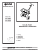
™ owners manual Model No. 45-0382 45-0405 45_0382Cvr 125 LB. PUSH BROADCAST SPREADER CAUTION: Read Rules for Safe Operation and Instructions Carefully • • • • • Safety Assembly Operation Maintenance Parts the fastest way to purchase parts PRINTED IN USA www.speedepart.com FORM NO. 49905 (REV.
RULES FOR SAFE OPERATION The following precautions are suggested. This broadcast spreader is designed, engineered and tested to offer reasonably safe and effective service, provided it is operated in strict accordance with these instructions. Failure to do so may result in personal injury. Always observe the rules of safe operation. LOOK FOR THIS SYMBOL TO POINT OUT IMPORTANT SAFETY PRECAUTIONS. IT MEANS — ATTENTION! BECOME ALERT! YOUR SAFETY IS INVOLVED. 1. 2. 3. 4. 5. 6.
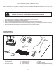
HARDWARE PACKAGE CONTENTS (Shown full size except where noted) Key Qty. Description Key A B C D E F G H 3 8 1 1 12 3 1 6 Hex Bolt, 1/4-20 x 2-1/2 in. Long Hex Bolt, 1/4-20 x 1-1/2 in. Long Hex Bolt, 1/4-20 x 3/4 in. Long Carr. Bolt,1/4-20 x 3/4 in. Long Nylock Nut, 1/4-20 Washer, 1/4 in. SS Washer, Nylon Washer, 5/8 ID x 1 in. OD Qty. Description I 1 J 2 K 1 L 1 M 1 N 2 O 1 P 2 Q 1 Cotter Pin, 5/32 x 2 in. Cotter Pin, 9/64 x 1-1/2 in. Cotter Pin, 1/8 x 3/4 in.
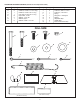
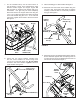
ENGLISH ASSEMBLY INSTRUCTIONS 5/32 x 2 in. COTTER PIN (I) TOOLS REQUIRED FOR ASSEMBLY (1) Pliers (2) 7/16 in. open or boxed end wrenches 9/64 x 1-1/2 in. COTTER PIN (J) 5/8 in. FLAT WASHER (H) 1. Remove the spreader, the loose parts and the hardware package from the carton. Lay out parts and hardware and identify using the illustrations on pages 2 and 3. 2. With the spreader resting upside down on the top of the hopper, assemble a 5/8 in. flat washer, a spacer and a second 5/8 in.
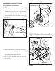
7. For the standard setup, use the holes shown in the illustration. Other hole combinations allow different handle heights and hopper angles. Do not use holes in stand that are farthest apart as a combination - flow gate may not close completely. Attach the stand to the hopper frame tube using two 1/4 x 1-1/2 in. bolts and nylock nuts. Attach the stand to the lower handle using two 1/4 x 1-1/2 in. bolts and nylock nuts. Tighten all four bolts to secure the stand. See figure 4. USE MIDDLE HOLE 9.
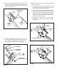
12. Insert the end of the flow control rod through the slot in the flow control mounting bracket and through the hole in the flow control lever. Secure with a 1/8 in. x 3/4 in. cotter pin. See figure 8. 14. Adjust the position of the flow control mounting bracket (figures 10 and 11): a. Set the adjustable stop at “5.” Latch the flow control lever against the stop. Verify that the closure plate has opened about halfway. See figure 10. 1/8 x 3/4 in. COTTER PIN (K) b.
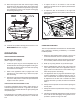
15. Place the hopper screen down into the hopper, sliding the ends into the clips in the hopper. The screen helps break up clumpy material and prevents large clumps from reaching the bottom of the hopper and clogging the opening. See figure 12. 1. To adjust the flow to be heavier to the left side, tighten the thumbscrew so the plate is pushed inward. See figure 13 2. To adjust the flow to be heavier to the right side, loosen the thumbscrew so the plate is pulled outwards.
IMPORTANT: Application rates shown in the chart are affected by humidity and by the moisture content of the material (granular and pellet). Some minor setting adjustments may be necessary to compensate for this condition. 9. To insure uniform coverage, make each pass so that the broadcast pattern slightly overlaps the pattern from the previous pass as shown in figure 14. The approximate broadcast widths for different materials are shown in the Application Diagram figure 14. 10.
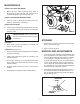
MAINTENANCE CHECK FOR LOOSE FASTENERS GREASE 1. Before each use, make a thorough visual check of the spreader for any bolts and nuts which may have loosened. Retighten any loose bolts and nuts. OIL CHECK FOR WORN OR DAMAGED PARTS 2. Check for worn or damaged parts before each use. Repair or replace parts if necessary. CHECK TIRE INFLATION 3. Check if tires are adequately inflated before each use. Do not inflate tires beyond maximum recommended pressure on tire.
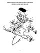
REPAIR PARTS FOR BROADCAST SPREADER MODEL 45-0382 AND 45-0405 55 9 8 7 6 9 12 8 1 6 31 52 41 20 45 37 4 42 18 10 25 19 20 7 6 54 30 44 43 46 48 47 7 17 50 49 10 16 15 27 10 13 11 29 22 14 56 53 39 40 35 10 10 25 24 32 33 39 26 10 4 21 48 34 2 25 33 27 36 3 28 32 5 39 40 21 5 4 25 25 35 36 38 3 10 10 10 4 25 54 23
REPAIR PARTS FOR BROADCAST SPREADER MODEL 45-0382 AND 45-0405 Ref. No. Part No. Qty. Description Ref. No. Part No. Qty. 29 47205 1 1 44466 1 Hopper, Spreader (125 lb.
the fastest way to purchase parts REPAIR PARTS Agri-Fab, Inc. 809 South Hamilton Sullivan, IL 61951 217-728-8388 www.agri-fab.com © 2006 Agri-Fab, Inc. www.speedepart.