
Manual

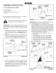
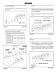


20.Turntheaeratorrightsideupandassemblethefront
endsofthehitcharmstogetherusingtwo5/16"x 1-1/4"
hexbolts(O)and5/16"nylocknuts(G).Donottighten
yet.Seefigure13.
21.Assemblethetwohitchbracketstothetopandbottom
ofthehitcharmsusingtwo5/16"x 2"hexbolts(B)and
5/16"nylocknuts(G).Donottightenyet. See figure
13.
22. Assemble the 3/8" hitch pin (J) through the hitch brackets
and secure it with a 1/8" hair cotter pin (I). See figure
13.
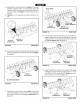
25. Assemble the lift handle through the tray and attach it
to the hitch arm mount bracket assembled to the axle
bracket. Use a 5/16" x 1" hex bolt (D) and a 5/16" nylock
nut (G). Tighten. See figure 15.
26. Position the hitch arm mount bracket so that there is
side tension on the lift handle when it is locked in the
up position. Tighten the nuts. See figure 15.
27. Assemble the grip (T) onto the end of the lift handle.
See figure 15.
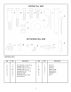
(B) 5/16" x 2"
HEXBOLT
' ! N LOCKNUT
(c)5/16"x1-1/4"
HEX BOLT / _._.._
(G)5/16"NYLOCKNUT_ --(l) 1/6"HAIR
COTTER PIN
FIGURE 13 FRONT VIEW
23. Tighten the bolts and nuts assembled instep 20. Tighten
the bolts and nuts assembled in step 21.
Tighten the bolts and nuts assembled instep 18. Tighten
the bolts and nuts assembled in step 3. Tighten the
bolts and nuts assembled in step 17.
GRIP
LIFT HANDLE
J
(G) 5/16" NYLOCK NUT
(D) 5/16" x 1"
HEX BOLT
24. Assemble a hitch arm mount bracket to the axle bracket
using two 5/16" x 1" carriage bolts (E) and 5/16" nylock
nuts (G). Do not tighten yet. See figure 14.
FIGURE 15 REAR VIEW
(E) 5116" x 1"
CARRIAGE BOLT
(G) 5116"NYLOCK NUT
FIGURE 14 REAR VIEW
8