
Instructions / Assembly


7
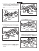
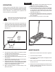
FIGURE 11 FRONT VIEW
FIGURE 12 FRONT VIEW
(G) 5/16"
NYLOCK NUT
(D) 5/16" x 1"
HEX BOLT
(O) ANGLE
BRACKET
(D) 5/16" x 1"
HEX BOLT
(G) 5/16"
NYLOCK NUT
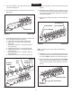
FIGURE 10 REAR VIEW
FIGURE 9 REAR VIEW
(F) 3/8"
NYLOCK NUT
(A) SHOULDER BOLT
HITCH ARMS
(E) 5/16" x 1"
CARRIAGE BOLT
(G) 5/16"
NYLOCK NUT
HITCH ARM
MOUNT BRACKET
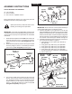
FIGURE 8 REAR VIEW
(D) 5/16" x 1"
HEX BOLT
(G) 5/16"
NYLOCK NUT
ENGLISH
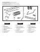
16. Assemble the wheels to the axle bracket using a shoulder
bolt (A) and a 3/8" nylock nut (F) for each wheel. Tighten.
Seegure9.
17. Assemble the hitch arms to the outside of the hitch
arm mount brackets. Use two 5/16" x 1" carriage bolts
(E) and 5/16" nylock nuts (G). Do not tighten yet. See
gure10.
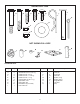
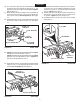
18. Turn the tray so that the front faces you. Assemble two
angle brackets (O) to the holes in the bottom of the tray
using two 5/16" x 1" hex bolts (D) and 5/16" nylock nuts
(G). Do not tighten yet.Seegure11.
19. Fasten the hitch mount arms to the outside of the angle
brackets at the front of the tray using two 5/16" x 1" hex
bolts (D) and 5/16" nylock nuts (G). Tighten and then
loosenthenuts1/4turn.Seegure12.
14. Assemble the axle bracket to the outside of the angle
brackets using two 5/16" x 1" hex bolts (D) and 5/16"
nylock nuts (G). The ends of the axle bracket must point
asshowningure8.Tighten and then loosen the nuts
1/4 turn.
15. Tighten the nuts fastening the angle brackets to the
tray.