
Instructions / Assembly


5
ASSEMBLY INSTRUCTIONS
TOOLS REQUIRED FOR ASSEMBLY
(2) 1/2" wrenches
(1) 9/16" wrenches
(1) 3/4" wrench or adjustable wrench
Before assembling the aerator, lay out all of the parts and
hardware as shown on the previous pages.
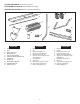
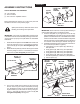
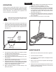
FIGURE 1 FRONT VIEW
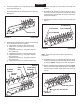
FIGURE 2 REAR VIEW
IMPORTANT: The points of the spike disks must be turned
in the direction shown in the assembly drawings. The aerator
will not perform properly if the spike disks are assembled
backwards.
(D) 5/16" x 1"
HEX BOLT
(G) 5/16" NYLOCK NUT
(D) 5/16" x 1"
HEX BOLT
(P) LIFT PLATE
AXLE
SUPPORT
BRACKET
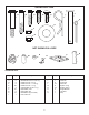
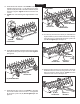
FIGURE 3 REAR VIEW
IMPORTANT: Be sure the rear of the tray faces toward you
and the spike disks point in the direction shown.
4. Pivot the end plate on your right down out of the way.
Place the long end of the axle into the other pivot plate.
(Measure from the blind hole in the middle of the axle. If
there are two blind holes, use the hole that is in alignment
with the end holes.) Fit the middle hole in the axle down
ontothetabontheaxlesupportbracket.Seegure3.
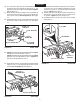
5. Assemble the following parts in sequence onto the short
endoftheaxle(asshowningure3):
a. Aatwasher(H),shortspacer(N),diskhub(L)
and spike disk
b. A long spacer (M), disk hub (L) and spike disk.
c. A long spacer (M), disk hub (L) and spike disk.
d. A long spacer (M), disk hub (L) and spike disk.
e. A long spacer (M), disk hub (L) and spike disk.
f. Two short spacers (N), a disk hub (L) and spike disk.
g. A short spacer (Q).
Spike points are sharp. Exercise caution when
handling and working near spike disks.
HITCH ARM
MOUNT
BRACKET
(G) 5/16"
NYLOCK
NUT
(D) 5/16" x 1"
HEX BOLT
(O) ANGLE
BRACKET
REAR OF TRAY
REAR OF TRAY
(N) SHORT
SPACER
(M) LONG
SPACER
(L) DISK
HUB
(H) FLAT
WASHER
SHORT END
LONG END
TAB ON AXLE
SUPPORT BRACKET
HOLE
(N) SHORT
SPACER
1. Assemble the end plates to the inside slots at each end
of the tray using two 5/16" x 1" hex bolts (D) and 5/16"
nylock nuts (G) per end plate. Do not tighten yet. See
gure1.
2. Assemble the lift plate (S) and the axle support bracket
to the tray using four 5/16" x 1" hex bolts (D) and 5/16"
nylock nuts (G). Do not tighten yet.Seegure1.
3. Turnthetrayupsidedownasshowningure2sothat
the rear of the tray (four holes in the bottom) is facing
you. Assemble two hitch arm mount brackets and two
angle brackets (O) to the bottom of the tray using four
5/16" x 1" hex bolts (D) and 5/16" nylock nuts (G). Do
not tighten completely.Seegure2.
ENGLISH