
Installation Guide


8
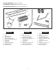
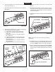
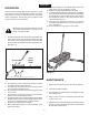
FIGURE 14 REAR VIEW
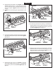
FIGURE 15 REAR VIEW
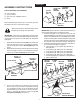
FIGURE 13 FRONT VIEW
(G) 5/16" NYLOCK NUT
(I) 1/8" HAIR
COTTER PIN
(C) 5/16" x 1-1/4"
HEX BOLT
(B) 5/16" x 2"
HEX BOLT
(J) 3/8" HITCH PIN
(G) 5/16"
NYLOCK NUT
(E) 5/16" x 1"
CARRIAGE BOLT
(G) 5/16" NYLOCK NUT
(G) 5/16" NYLOCK NUT
(D) 5/16" x 1"
HEX BOLT
LIFT HANDLE
(T) GRIP
20. Turntheaeratorrightsideupandassemblethefront
endsofthehitcharmstogetherusingtwo5/16"x1-1/4"
hexbolts(C)and5/16"nylocknuts(G).Do not tighten
yet. Seegure13.
21. Assemblethetwohitchbracketstothetopandbottom
ofthehitcharmsusingtwo5/16"x2"hexbolts(B)and
5/16"nylocknuts(G).Do not tighten yet. Seegure
13.
22. Assemblethe3/8"hitchpin(J)throughthehitchbrackets
andsecureitwitha1/8"haircotterpin(I).Seegure
13.
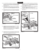
23. Tightentheboltsandnutsassembledinstep20.Tighten
theboltsandnutsassembledinstep21.
Tightentheboltsandnutsassembledinstep18.Tighten
thebolts andnutsassembledinstep3.Tightenthe
boltsandnutsassembledinstep17.
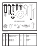
24. Assembleahitcharmmountbrackettotheaxlebracket
usingtwo5/16"x1"carriagebolts(E)and5/16"nylock
nuts (G). Do not tighten yet.Seegure14.
25. Assemblethelifthandlethroughthetrayandattachit
tothehitcharmmountbracketassembledtotheaxle
bracket.Usea5/16"x1"hexbolt(D)anda5/16"nylock
nut (G). Tighten.Seegure15.
26. Positionthehitcharmmountbracketsothatthereis
sidetensiononthelifthandlewhenitislockedinthe
up position. Tightenthenuts.Seegure15.
27. Assemblethegrip(T)ontotheendofthelifthandle.
Seegure15.
ENGLISH