
Spreader User Manual

7
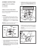
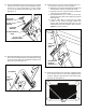
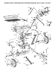
25. Positiontheowcontrolmountingbracket(gure14).
a. Pushowcontrolarmto"OFF"position.
b. Slideowcontrolmountingbracketalongtubeuntil
closureplateinbottomofhopperjustcloses.
c. Snugthe5/16"locknutsjustenoughtoholdow
controlmountingbracketinplace.
d. Set adjustable stop at "5". Pull ow control arm
against stop. Verify that closure plate has opened
abouthalfway.
e. If closure plate does not open half way, adjust
position of ow control mounting bracket until
closureplatewillopenabouthalfwayat"5"and
willstillclosewhenarmislockedin"OFF"position.
Tightenthe5/16"locknuts.
FIGURE 14
FIGURE 12
FLOW
CONTROL
ARM
OFF
ON
1
2
3
4
6
7
8
9
10
5
ADJUSTABLE
STOP (S)
(SETTING "5")
ON
OFF
(R) NYLON
WING NUT
OFF
ON
1
2
3
4
6
7
8
9
10
5
(K) 5/16" FLAT
WASHER
(J) NYLON
WASHER
(S) ADJUSTABLE
STOP
(F) 1/4" x 3/4"
CARRIAGE BOLT
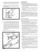
26. Placethescreendownintothehopper,slidingtheedge
ofthescreenunderoneoftheclips.Slightlybowthe
screen to slide the opposite side of the screen under
theotherclip.Seegure15.
FIGURE 15
CLIPS
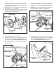
23. Placetheadjustablestop(S)intothe"ON"endoftheslot
inthetopoftheowcontrolmountingbracket.Secure
withthe1/4"x3/4"carriagebolt(F),anylonwasher
(J),a5/16"atwasher(K)andthenylonwingnut(R).
Seegure12.
OFF
ON
1
2
3
4
6
7
8
9
10
5
(X) SPRING
FLOW
CONTROL
ROD
FIGURE 13
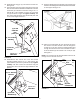
24. Slidetheadjustablestoptotheendoftheslot.Movethe
owcontrolarmagainstthestop.Assemblethespring
(X)totheowcontrolmountingbracketandthentothe
owcontrolrod.Seegure13.